D-Link DES-3250TG Standalone Layer 2 Switch
The AC power connector is a standard
Side Panels
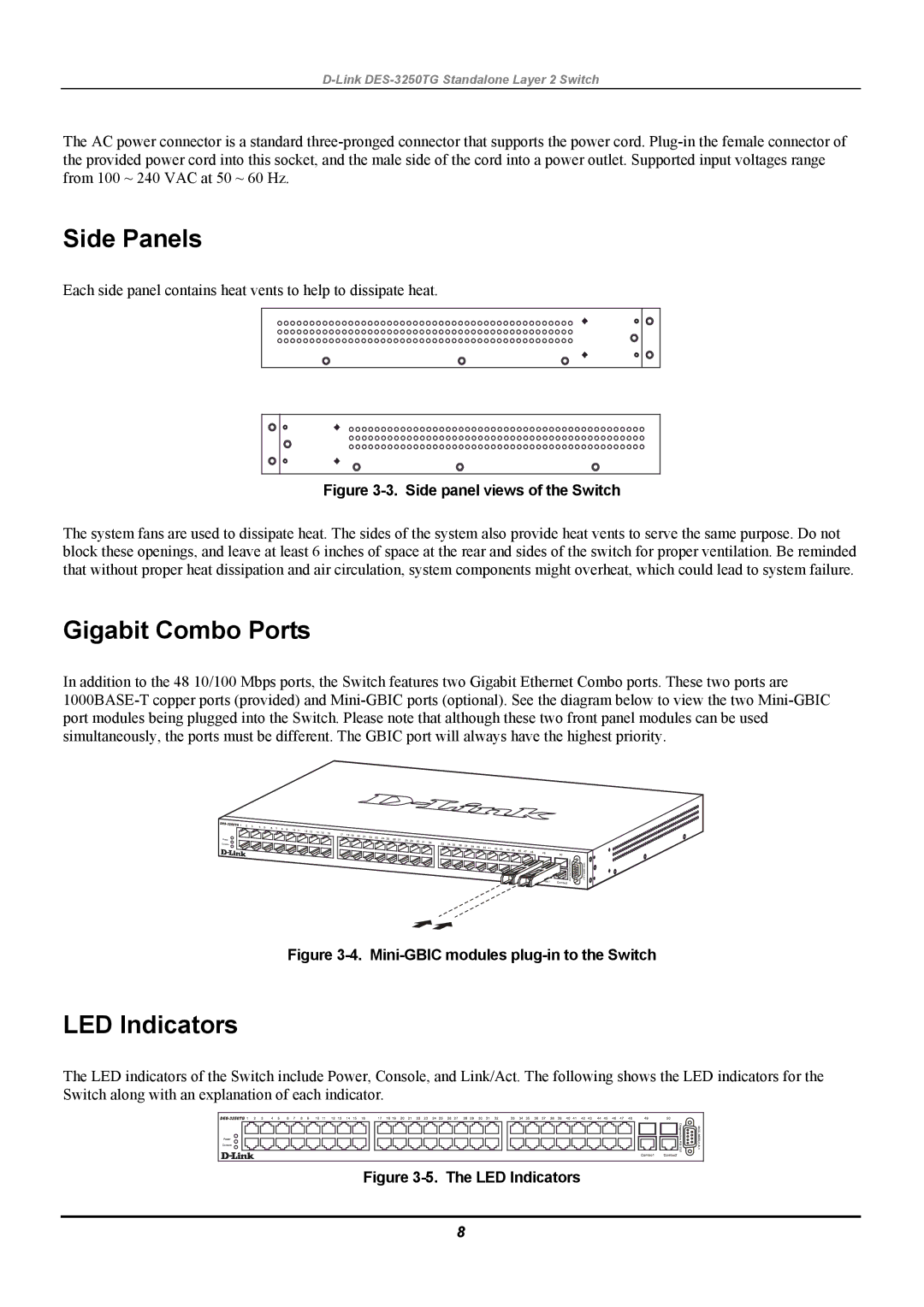
Each side panel contains heat vents to help to dissipate heat.
Figure 3-3. Side panel views of the Switch
The system fans are used to dissipate heat. The sides of the system also provide heat vents to serve the same purpose. Do not block these openings, and leave at least 6 inches of space at the rear and sides of the switch for proper ventilation. Be reminded that without proper heat dissipation and air circulation, system components might overheat, which could lead to system failure.
Gigabit Combo Ports
In addition to the 48 10/100 Mbps ports, the Switch features two Gigabit Ethernet Combo ports. These two ports are
Figure 3-4. Mini-GBIC modules plug-in to the Switch
LED Indicators
The LED indicators of the Switch include Power, Console, and Link/Act. The following shows the LED indicators for the Switch along with an explanation of each indicator.
Figure 3-5. The LED Indicators
8