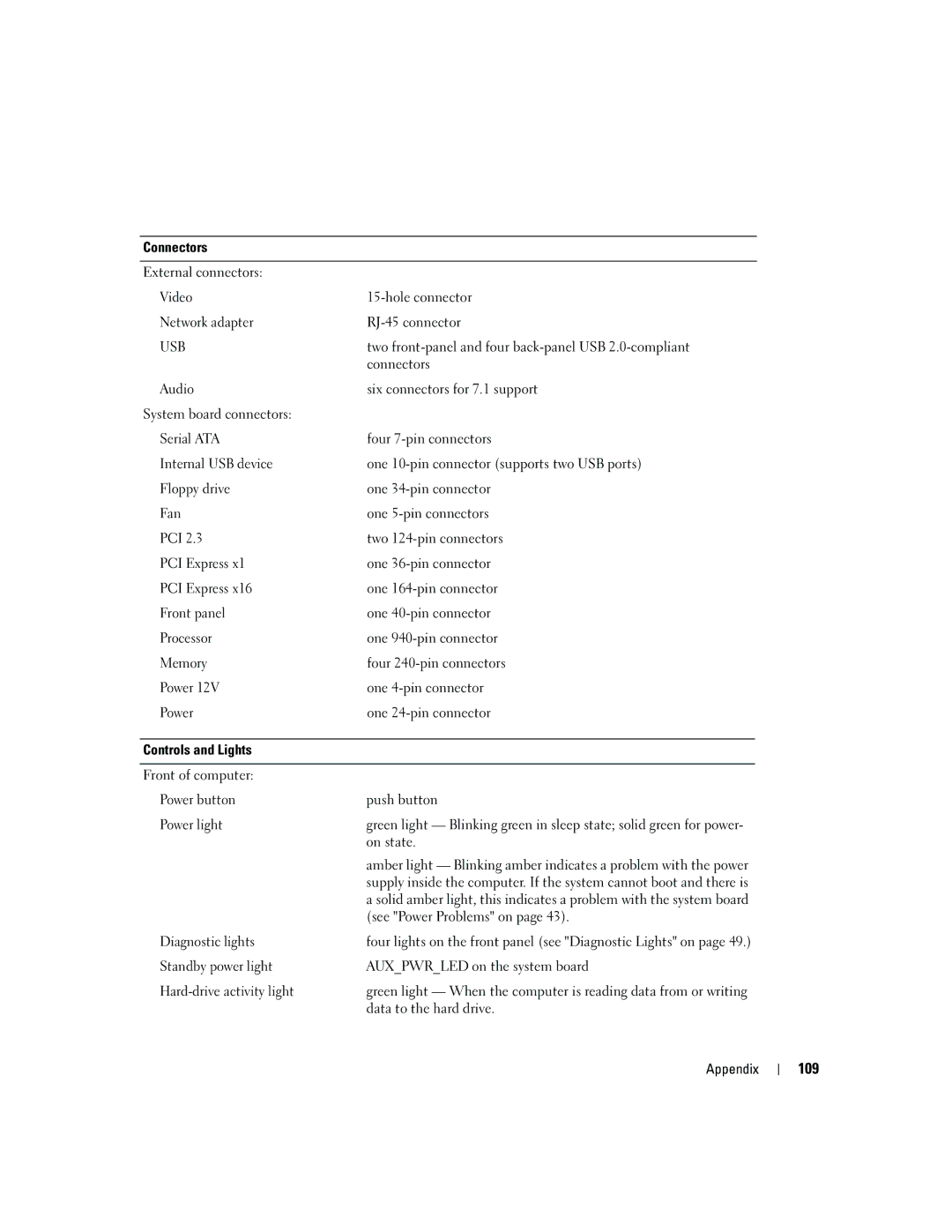
Connectors
External connectors:
Video | |
Network adapter | |
USB | two |
| connectors |
Audio | six connectors for 7.1 support |
System board connectors: |
|
Serial ATA | four |
Internal USB device | one |
Floppy drive | one |
Fan | one |
PCI 2.3 | two |
PCI Express x1 | one |
PCI Express x16 | one |
Front panel | one |
Processor | one |
Memory | four |
Power 12V | one |
Power | one |
|
|
Controls and Lights |
|
|
|
Front of computer: |
|
Power button | push button |
Power light | green light — Blinking green in sleep state; solid green for power- |
| on state. |
| amber light — Blinking amber indicates a problem with the power |
| supply inside the computer. If the system cannot boot and there is |
| a solid amber light, this indicates a problem with the system board |
| (see "Power Problems" on page 43). |
Diagnostic lights | four lights on the front panel (see "Diagnostic Lights" on page 49.) |
Standby power light | AUX_PWR_LED on the system board |
green light — When the computer is reading data from or writing | |
| data to the hard drive. |
Appendix
