State Name | Slot/Device State | Status LED (Green) | Status LED (Amber) |
|
|
|
|
Device identify (blink) | The device is identifying the | On for 250 msec | Off |
| slot location or is indicating | Off for 250 msec |
|
| the device has received a |
|
|
| Prepare for Removal |
|
|
| command from the host |
|
|
| operating system. |
|
|
Device failed | The host operating system | Off |
| no longer has access to the |
|
| device because the device |
|
| is not responding or has |
|
| encountered a critical error |
|
| condition. |
|
On for 250 msec Off for 250 msec
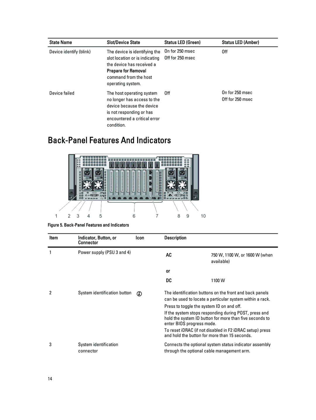
Back-Panel Features And Indicators
Figure 5. Back-Panel Features and Indicators
Item | Indicator, Button, or | Icon | Description |
|
| Connector |
|
|
|
|
|
|
|
|
1 | Power supply (PSU 3 and 4) |
| AC | 750 W, 1100 W, or 1600 W (when |
|
|
| ||
|
|
|
| available) |
|
|
| or |
|
|
|
| DC | 1100 W |
2 | System identification button |
| The identification buttons on the front and back panels | |
|
|
| can be used to locate a particular system within a rack. | |
|
|
| Press to toggle the system ID on and off. | |
|
|
| If the system stops responding during POST, press and | |
|
|
| hold the system ID button for more than five seconds to | |
|
|
| enter BIOS progress mode. | |
|
|
| To reset iDRAC (if not disabled in F2 iDRAC setup) press | |
|
|
| and hold the button for more than 15 seconds. | |
3 | System identification |
| Connects the optional system status indicator assembly | |
| connector |
| through the optional cable management arm. | |
14
