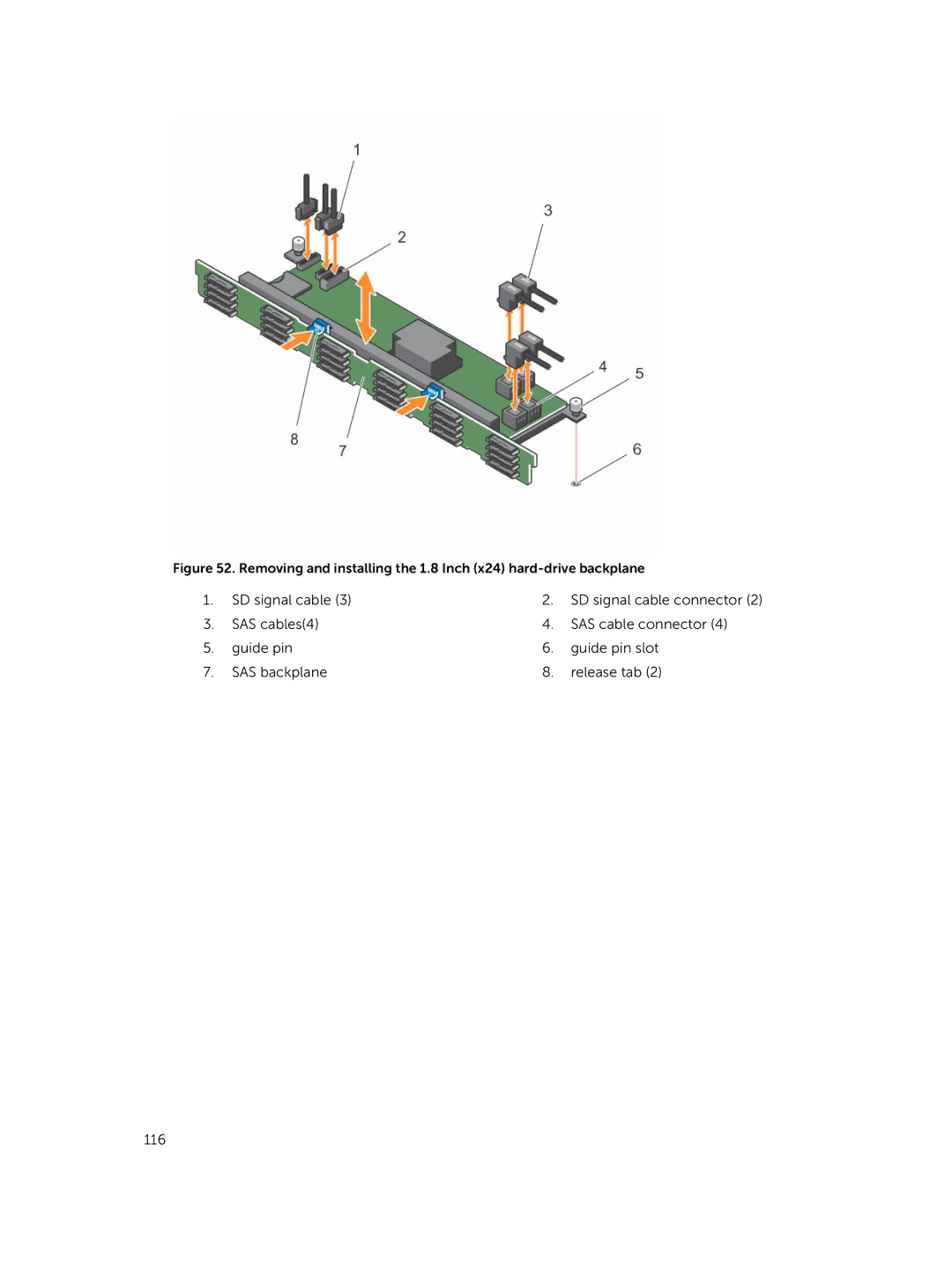
Figure 52. Removing and installing the 1.8 Inch (x24) hard-drive backplane
1. | SD signal cable (3) | 2. SD signal cable connector (2) | |
3. | SAS cables(4) | 4. | SAS cable connector (4) |
5. | guide pin | 6. | guide pin slot |
7. | SAS backplane | 8. | release tab (2) |
116