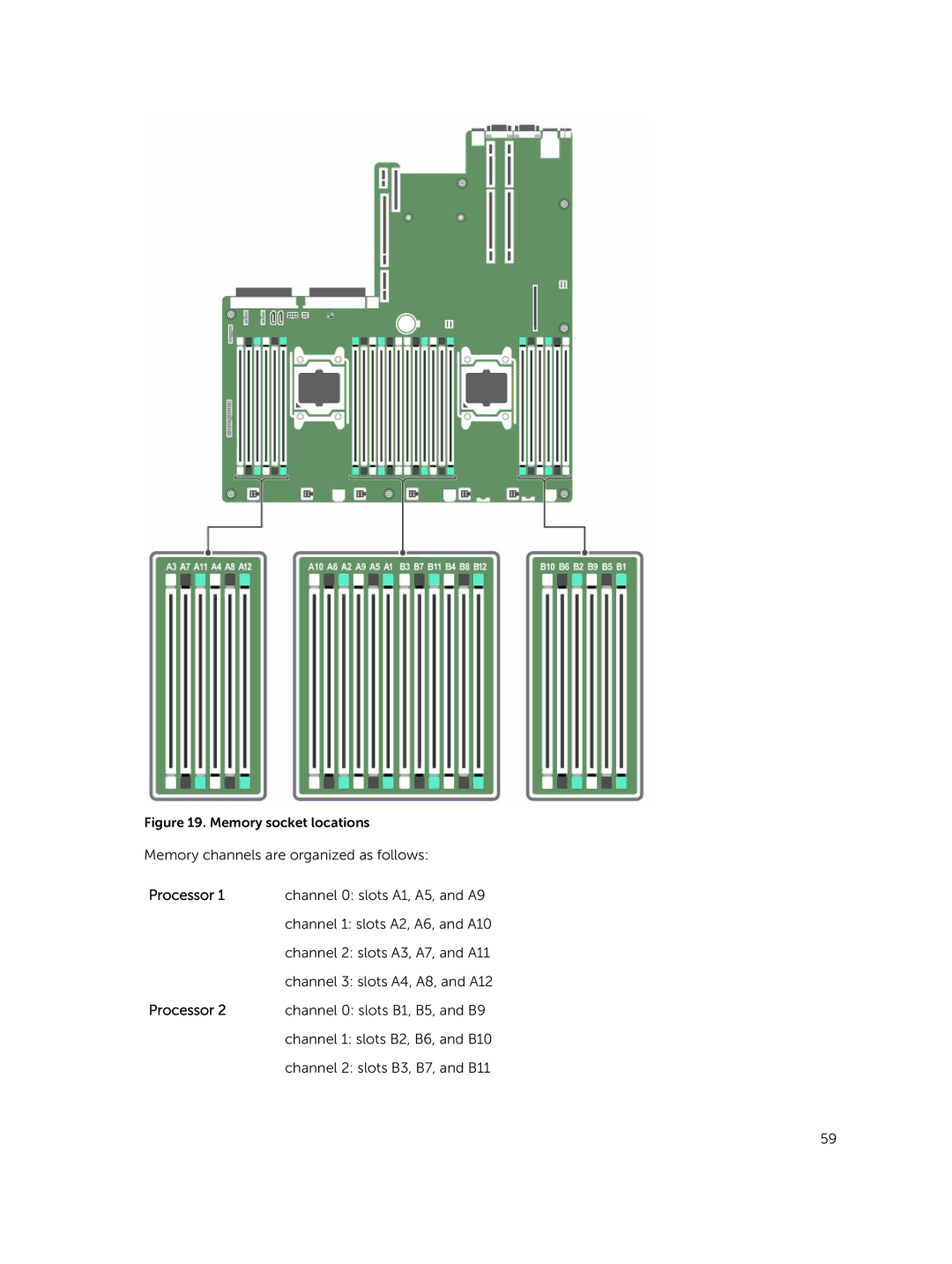
Figure 19. Memory socket locations Memory channels are organized as follows:
Processor 1 | channel 0: slots A1, A5, and A9 |
| channel 1: slots A2, A6, and A10 |
| channel 2: slots A3, A7, and A11 |
| channel 3: slots A4, A8, and A12 |
Processor 2 | channel 0: slots B1, B5, and B9 |
| channel 1: slots B2, B6, and B10 |
| channel 2: slots B3, B7, and B11 |
59