Item | Indicator, Button, or | Icon | Description |
| Connector |
|
|
|
|
|
|
|
|
| bezel. This feature allows management of the |
|
|
| system using mobile devices. This feature |
|
|
| aggregates hardware/firmware inventory and |
|
|
| various system level diagnostic/error information |
|
|
| that can be used in troubleshooting the system. |
|
|
| For more information, see the Integrated Dell |
|
|
| Remote Access Controller User’s Guide at |
|
|
| dell.com/esmmanuals. |
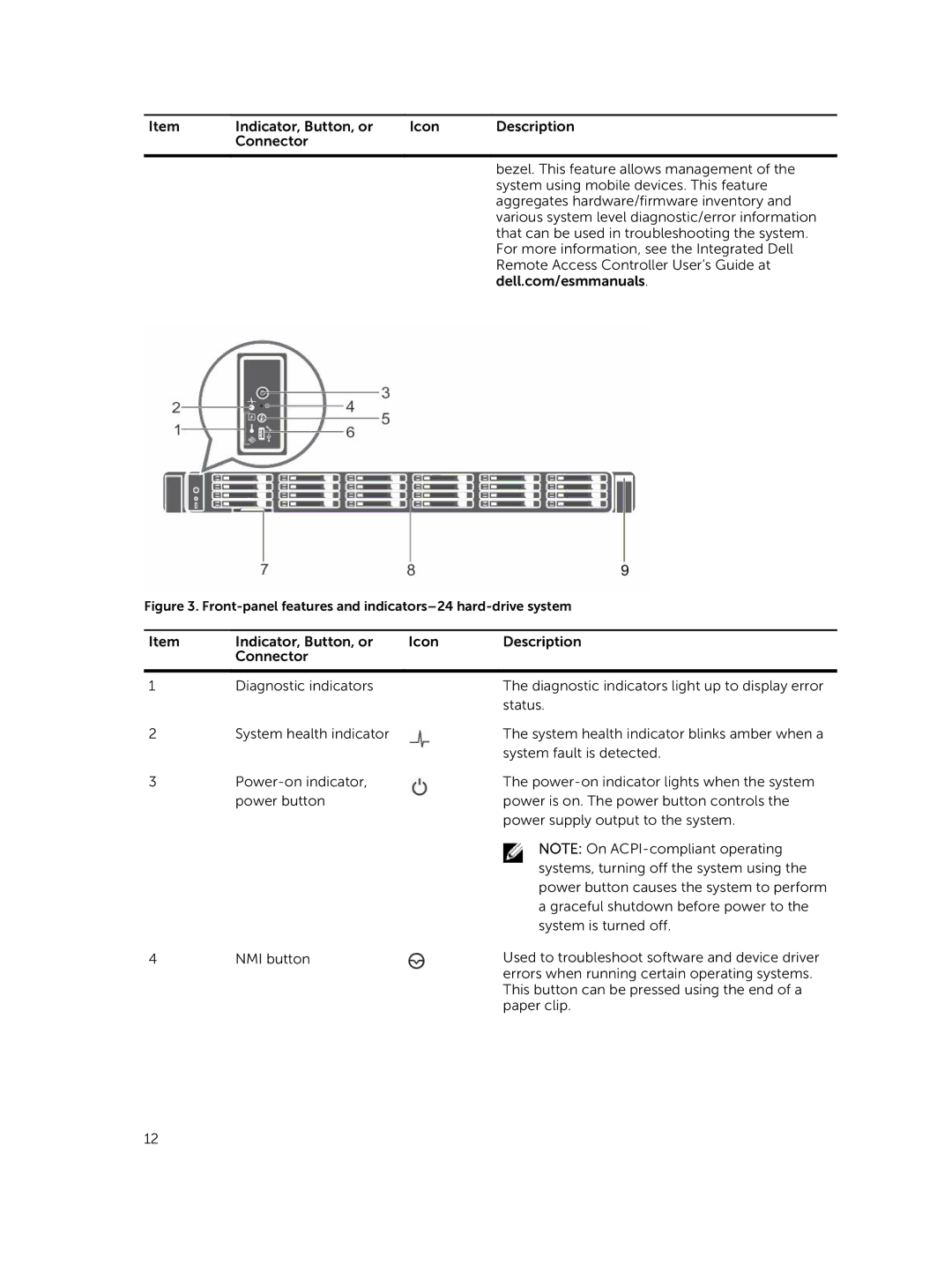
Figure 3. Front-panel features and indicators–24 hard-drive system
Item | Indicator, Button, or | Icon | Description |
| Connector |
|
|
|
|
|
|
1 | Diagnostic indicators |
| The diagnostic indicators light up to display error |
|
|
| status. |
2 | System health indicator |
| The system health indicator blinks amber when a |
|
|
| system fault is detected. |
3 |
| The | |
| power button |
| power is on. The power button controls the |
|
|
| power supply output to the system. |
|
|
| NOTE: On |
|
|
| systems, turning off the system using the |
|
|
| power button causes the system to perform |
|
|
| a graceful shutdown before power to the |
|
|
| system is turned off. |
4 | NMI button |
| Used to troubleshoot software and device driver |
errors when running certain operating systems. This button can be pressed using the end of a paper clip.
12