Management Terminal Setup
To connect the switch module to a PC or compatible device running the VT terminal emulation, proceed as follows:
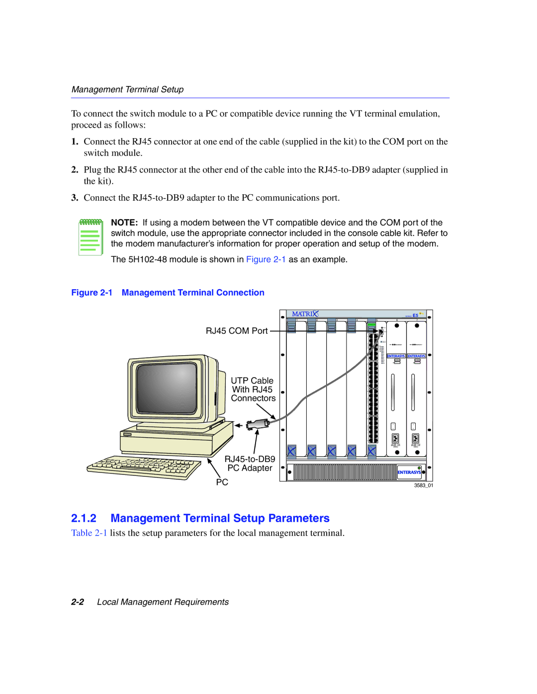
1.Connect the RJ45 connector at one end of the cable (supplied in the kit) to the COM port on the switch module.
2.Plug the RJ45 connector at the other end of the cable into the
3.Connect the
NOTE: If using a modem between the VT compatible device and the COM port of the switch module, use the appropriate connector included in the console cable kit. Refer to the modem manufacturer’s information for proper operation and setup of the modem.
The
Figure 2-1 Management Terminal Connection
RJ45 COM Port
UTP Cable
With RJ45
Connectors
PC Adapter
PC
|
|
|
|
| SERIES | E5 |
1 | 2 | 3 | 4 | 5 | 6 | 7 |
|
|
|
| FAST ENET |
|
|
|
|
|
|
|
| |
|
|
|
|
| RESET |
|
|
|
|
|
| COM |
|
1X | CPU |
| GROUP |
| |
G | SELECT |
| |
R | GROUP |
O | |
U |
|
P |
|
1 |
|
11X
13X
G
R
O
U
P
2
23X
25X
G
R
O
U
P
3
35X
37X
G
R
O
U
P
4
47X |
3583_01
2.1.2Management Terminal Setup Parameters
Table