Enterasys Networks 5H1XX, 5G1XX manual Spanning Tree Protocol in a Network

Models: 5G1XX 5H1XX

1 144
Download 144 pages 52.79 Kb
Page 128
Image 128

Spanning Tree Protocol in a Network

A.2 SPANNING TREE PROTOCOL IN A NETWORK

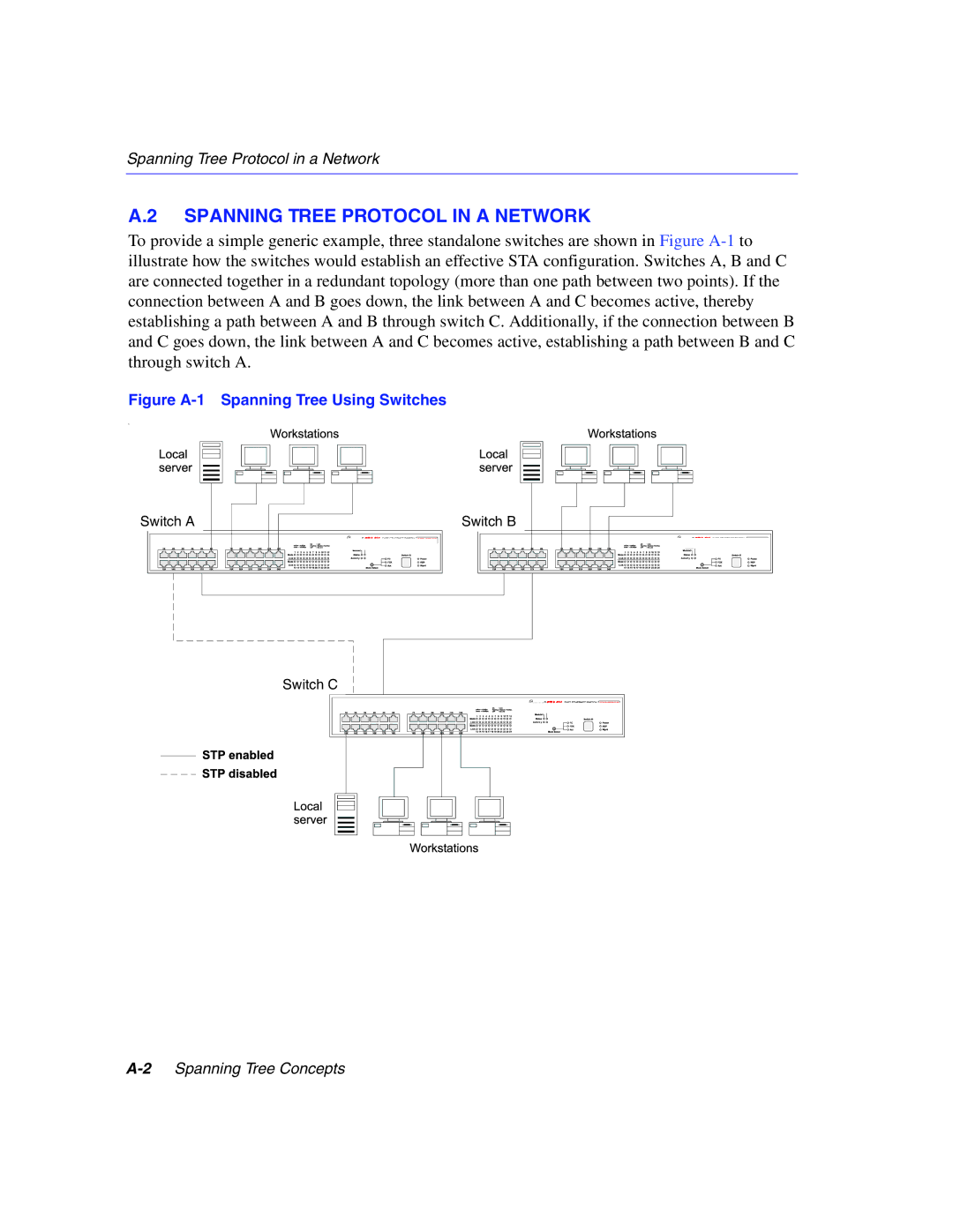
To provide a simple generic example, three standalone switches are shown in Figure A-1to illustrate how the switches would establish an effective STA configuration. Switches A, B and C are connected together in a redundant topology (more than one path between two points). If the connection between A and B goes down, the link between A and C becomes active, thereby establishing a path between A and B through switch C. Additionally, if the connection between B and C goes down, the link between A and C becomes active, establishing a path between B and C through switch A.

Figure A-1 Spanning Tree Using Switches

s

Switch A

Switch B

Switch C

A-2Spanning Tree Concepts

Page 128
Image 128
Enterasys Networks 5H1XX, 5G1XX manual Spanning Tree Protocol in a Network