Manuals
/
Epson
/
Computer Equipment
/
Printer
Epson
N2700
manual
Models:
N2700
1
164
165
165
Download
165 pages
6.34 Kb
158
159
160
161
162
163
164
165
Troubleshooting
Specifications
Install
Parts list
Error codes
Appendix Exploded Diagrams 143
Controller Related Error List
LED Indicators
Maintenance
Image Quality Problems
Page 164
Image 164
Page 163
Page 165
Page 164
Image 164
Page 163
Page 165
Contents
Epson EPL-N2700
Page
Precautions
Safety Information
Laser Beam
Preface
Revision Issued Date Description
Contents
Troubleshooting
Appendix
Product Description
Software
Engine Features
Controller Features
Controller Specifications
CPU
RAM
ROM
Configuration
Installation Format
Other Feature
Interfaces
Engine Specifications
Paper Supply / Paper Size / Capacity
Paper Specifications
Paper Sources and their Paper Availability
Consumables and Options
Supported Paper Sizes
Paper Feed Alignment
Paper Ejection
Power Supply Specification
Consumption
Noise
Ozone Density
Process Specifications
Paper Type
Paper Path Availability
Paper Path Availability
Printable Area
Special Paper Standard Normal
Reliability, Durability, And Maintainability
Skew
Durability
Maintainability
Ejection Curl
Temperature and Humidity Vibration Tolerance
13. Environmental Conditions Main Unit
AIR Pressure
Drop Tolerance
Electrical Specifications
Safety Approval
Specifications
Consumable Item
Environmental Condition for Storage and Transportation
Drop Test
Parallel I/F Serial I/F Ethernet I/F Type B I/F
Host Interface Usage Configurations
19. Host Interface Usage Configurations
Parallel Interface
Serial Interface
Ethernet I/F
20. Ethernet I\F Pin Assignment
Emulation Emulation Type Entity Type
Type-B I/F
21. Emulations Available
LED Indicators
Control Panel
LCD Panel
Buttons
This printer has a non-volatile memory Eeprom to
Panel Settings
Setting Items
SelecType Option 1/7
SelecType Option 2/7
24. SelecType Option 3/7
25. SelecType Option 4/7
26. SelecType Option 5/7
27. SelecType Option 6/7
Maintenance Menu *24
SelecType Option 7/7
Setting Item Description
Setting Item Setting value Default Value Setting method
MP Tray Size
MP Type
Multibin Settings and Corresponding Outbins Available
Output Tray Selection Specifications
LC1 to LC3 Type
Paper Source
Items of restriction on the paper tray
Quantity Printing Menu
Duplex Printing Menu
Items of restriction on the duplex printing
One-Touch Setting
31. One-Touch Setting Functions
Special Functions
32. Special Functions Available
Hex-Dump Mode
Eeprom Initialization
Updating the Program ROM
Copying the ROM Module
Maintenance Mode
Mode
Engine Status Sheet
Sample Engine Status Sheet
EPL-N2700 Revision a
LC1
Data name Storage location Count condition Clear condition
34. Exterior View of the Printer Main Body
Weight
Operating Principles
Printer Mechanism Operating Principles
When the optional duplex unit are installed
Optional cassettes
Gear/Roller Location
Gear/Roller Location
Electrical Component Layout
Electrical Component Layout
Location Name Function
Switches and Sensors
Switches and Sensors
Paper Feeding Section
MP Tray
MP Cassette Set Sensor Mechanism
Timing Roller Sensor Mechanism
Paper Size Detection Mechanism
Cassette
Cassette
Separators
12. Cassette 1 Paper Feeding Mechanism
Paper Size and Corresponding Actuator Condition
Actuators Paper Size
14. Cassette 1 Paper Empty Sensor Mechanism
16. Cassette 1 Right Door Detecting Sensor
Paper Feed
17. Registration Compensation
Printhead Unit Exposure Section
19. Printhead Unit Mechanism
Print Process Sequence
20. Print Process Sequence
Imaging Cartridge
Part Names and Functions of the Imaging Cartridge
Charging Section
Development Section
24. Toner Image Production
Transfer Section
25. Transfer Section Mechanism
Fusing Section
26. Fusing Section
28. Fuser Temperature Control
Paper Exit Section
29. Paper Exit Sensor Mechanism
Right Door Interlock Switch
Detection whether New or Used Imaging Cartridge
System Layout
Drive Section
Electrical Section
33. System Layout Electrical Section
Main Circuit Video Controller
Main Component in the Main Circuit Board
Main Components in the Main Circuit Board
Name Location Functions
Troubleshooting
Printer Messages
Message List
Printer Message
Message Type
Yyy
Message Descriptions
Service-call Error
Engine Related Error
Engine Related Error List
Error Code Description
Error Code ffff Description
Controller Related Error List
Controller Related Error List
Troubleshooting
Clearing the Service-call Error
Troubleshooting The Printer will not Start
Adding on RAM
Image Quality Problems
Troubleshooting The Printer will not Print
Troubleshooting Image Quality Problem
Printer will no Print
DISASSEMBLY/ASSEMBLY
Precaution
Unplug the power code from the AC socket
Tools
Tool List
Reference No Size Name Appearance
Small Parts
Small Part Classification
Binding head B-tite Screw
Disassembly Procedure
ROM Dimm Replacement
ROM Dimm Removal
Paper Eject Sensor Removal
Paper Eject Sensor Removal
MP Cassette Paper Take-up Roller Removal
Taking out the MP Cassette
Never touch the transfer roller surface with your bare
Transfer Section
Transfer Roller Removal
Transfer Unit Removal
Timing Roller Front Sensor Removal
Timing Clutch Removal
13. Timing Clutch Removal
Timing Roller Removal
14. Timing Roller Removal
Outward
Separating the Printer
Internal Cooling Fan Removal
Rear Cover Removal
Transport Motor Removal
8 I/C Drive Motor Removal
MP Cassette Size Sensor Removal
Paper Size Sensor Removal
Top Cover Removal
Toner Empty Sensor Removal
23. Toner Empty Sensor Removal
Main Circuit Board Removal
24. Main Circuit Board Removal
Engine Controller Board Removal
25. Engine Controller Board Removal
Disassembly/Assembly 106
Power Supply Unit Cooling Fan Removal
With its exhausting side facing outside
High Voltage Unit Removal
29. High Voltage Unit Removal
Front Cover Removal
Control Panel Removal
Printhead Unit Removal
32. Lever / Left Cover Removal
Disassembly/Assembly 111
Power Supply Unit Removal
34. Harnesses to be Removed
Fusing Section
Fuser Unit Removal
Heater Lamp Replacement
38. Fuser Heater Lamp Front Cover Removal
Disassembly/Assembly 115
Disassembly/Assembly 116
Disassembly/Assembly 117
Upper Paper Separator Finger Removal
48. Fuser Lamp Termistor Removal
Lower Paper Separator Finger Removal
Upper Paper Eject Roller Removal
Lower Paper Eject Roller Removal
53. Lower Paper Eject Roller Removal
Drive Unit Removal
54. Fuser Unit Reinforce Plate Removal
Disassembly/Assembly 122
MP Cassette Paper Empty Sensor Removal
MP Cassette Paper Take-up Solenoid SL1 Removal
MP Cassette Set Sensor Removal
MP Cassette Paper Near Empty Sensor Removal
60. MP Cassette Paper Near Empty Sensor Removal
Roller is securely locked as shown below
Cassette 1 Disassembly
Paper Take-up Roller Removal
Cassette 1 Paper Empty Sensor Removal
Cassette 1 Paper Near Empty Sensor Removal
Paper Size Paper Size Switch Sensor Removal
Cassette 1 Control Board PWB-A Removal
Cassette 1 Paper Take-up Solenoid Removal
65. Cassette 1 Paper Take-up Solenoid Removal
Cassette 1 Right Door Set Sensor Removal
Error Indications and Measures
To cancel the updating at this point, press the Menu
Updating the Firmware
Updating the Program ROM
Disassembly/Assembly 131
Copying the Dimm Module
Adjustment
Adjustment 134
Maintenance
Maintenance by Users
Replacement of Consumable Items
User-performable Maintenance List
Replacement of Consumable Item
Maintenance by Servicers
Maintenance by Servicers
After replacing the Fusing Unit, perform Fuser
Replaced item Replacement cycle
Appendix
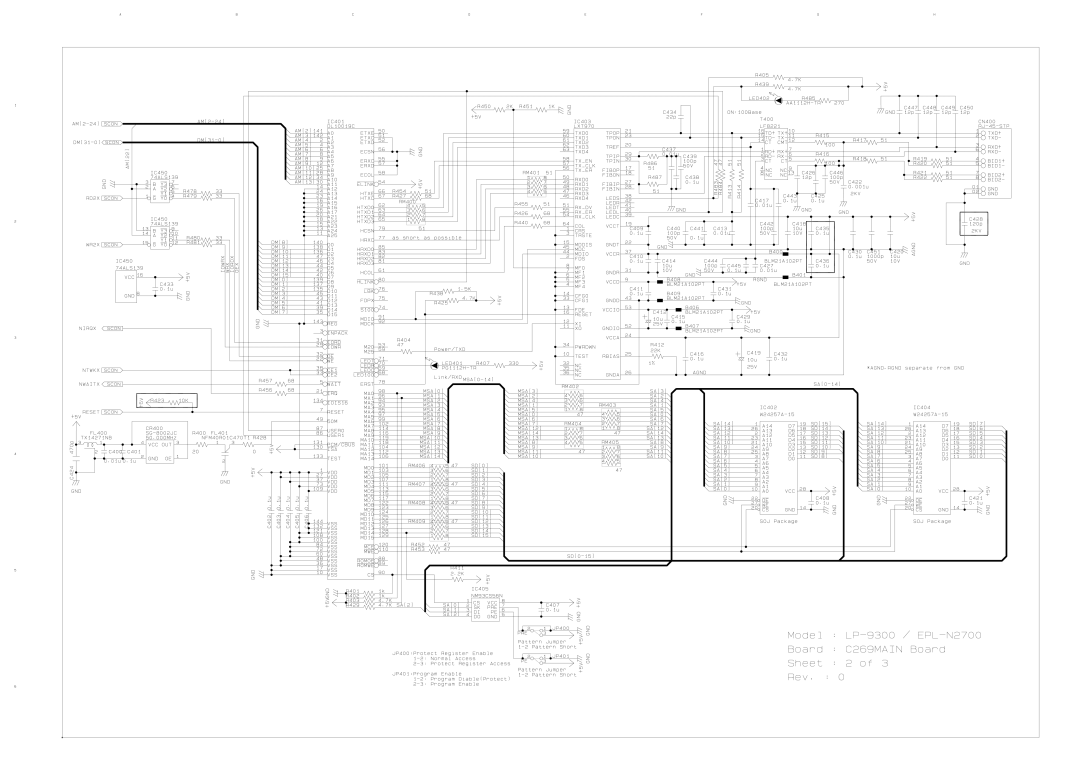
Connector Summary C269MAIN Circuit Board PWB-P
Connector Summary Engine Controller Board PWB-A
Connector Summary High Voltage Unit
Connector Summary Low Voltage Unit
Connector Number Constituent to which Other end
Pins Connector is connected Harness is connected
Component Layout
Ref. No Part Name
Housing
Parts List Housing
Appendix Exploded Diagrams 143
Parts List Frames
Frames
Appendix Exploded Diagrams 145
Parts List Fusing Section a
Fussing Section a
Appendix Exploded Diagrams 147
Fusing Section B
Parts List Fusing Section B
Appendix Exploded Diagrams 149
Parts List Transport Section a
Transport Section a
Appendix Exploded Diagrams 151
10. Parts List Transport Section B
Transport Section B
Appendix Exploded Diagrams 153
11. Parts List Electric Components
Electrical Components
Appendix Exploded Diagrams 155
12. Parts List Paper Take-up Section
Paper Take-up Section
Appendix Exploded Diagrams 157
13. Parts List Drive Section
Drive Section
Appendix Exploded Diagrams 159
14. Parts List Paper Tray Unit
Paper Tray Unit
Appendix Exploded Diagrams 161
Circuit Diagrams
Page
Top
Page
Image
Contents