About the BlackDiamond 12800 Series Switches
BlackDiamond 12802 Switch Chassis
The BlackDiamond 12802 chassis consists of the following components:
●One
●Two dedicated I/O module slots, labeled 1 and 2
●One MSM slot, labeled MSM
●Up to three redundant AC or DC power supplies, accessed from the back of the unit
●One fan tray, accessed from the back left of the unit
●One connector for an
●One PSU/fan controller that collects and reports data from the power supply units and the fan tray.
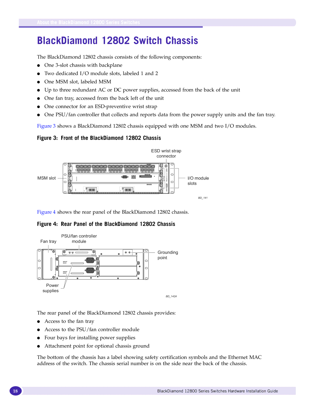
Figure 3 shows a BlackDiamond 12802 chassis equipped with one MSM and two I/O modules.
Figure 3: Front of the BlackDiamond 12802 Chassis
ESD wrist strap
connector
MSM slot
I/O module slots
BD_141
Figure 4 shows the rear panel of the BlackDiamond 12802 chassis.
Figure 4: Rear Panel of the BlackDiamond 12802 Chassis
| PSU/fan controller |
Fan tray | module |
Power |
|
supplies |
|
Grounding point
BD_142A
The rear panel of the BlackDiamond 12802 chassis provides:
●Access to the fan tray
●Access to the PSU/fan controller module
●Four bays for installing power supplies
●Attachment point for optional chassis ground
The bottom of the chassis has a label showing safety certification symbols and the Ethernet MAC address of the switch. The chassis serial number is on the side near the back of the chassis.
18 | BlackDiamond 12800 Series Switches Hardware Installation Guide |
|
|