DVS 304 Series
Avertissement
Achtung
Precaucion
Vorsicht
FCC Class a Notice
Extron Electronics. All rights reserved
Contents
Menu System
DVS 304 Series Description
Introduction
DVS 304 Models
DVS 304 DVI Models
Features
Memory and input presets
Four inputs
Controlling the DVS 304 Devices
Buffered video outputs
Options and Accessories
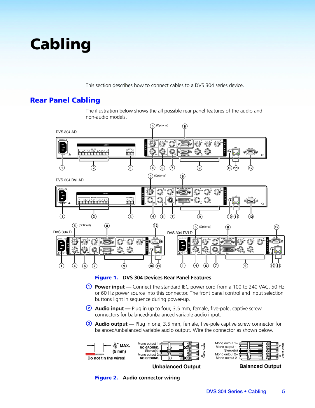
Cabling
Rear Panel Cabling
Pin
Video
Wiring the RJ-45
Input
Ground Signal ground Input
Pin RS-232 Function Description
No connection
Operation
Front Panel Overview
Menu Overview
Menus, Configuration, and Adjustments
Menu Navigation Using Front Panel Controls
Between them
Main Menu
Input Configuration
Start Auto Image
Input 3 video type
Input 1 video type
Input 2 video type
Input 4 video type
Output Configuration
Picture Control
Output Format
Resolutions and Refresh Rates
Sync Polarity
Memory Preset
Audio Configuration Audio Models Only
Memory Preset Per input Total
Recalling a preset
Save Memory Preset
Clear CLR memory preset
Input preset
IP Configuration
Advanced Configuration
RGB delay
Blue mode
Auto switch mode
Auto-Image
Test pattern
Enhance mode
OSD label
Refresh Lock
Auto Memory
Aspect Mode
Auto Memory and Auto Image Features
Auto Memory Per input Total
Picture-in-picture mode
Changing the input
Using the swap feature
Resetting an Input
Exit Menu
DVS 304 Reset Mode Summary
Resetting the Unit
Mode Activation Result Purpose and Notes
System Reset
Front Panel Lockout Executive Modes
Setting up the DVS to Work with a Matrix Switcher
DVS 304 Devices Connected to a Matrix Switcher
From the Tools menu, select Sync Scaler to Matrix Switcher
Sync DVS 304 to Matrix Switcher window opens
Removing the Sync to Matrix Script
DVS 304 Series Operation
SIS Communication Control
Pin RS-232 Function Description
Error Response References
Password Information
Error Responses
Error Numbers
Using the Command and Response Tables
Command and Responses
Telnet Web Browser
Symbol Definitions
Password is also removed
X7@ = Input selection 2 or
SIS Command Edid Table see
SIS Command and Response Table
Edid emulation for input 4 DVI models only
Input aspect ratio
Video mute
EI*X10*EDIDX6
Contrast
Color available for PAL and Ntsc only
Tint available for Ntsc composite and S-video only
Brightness
Output scaler rate
Zoom mode
Pan
Output sync format
Write and read input preset name inputs 4 presets only
Memory presets inputs 1 to
Input presets input 4 only
Audio mute audio models only
Auto switch mode
Volume control audio models only
RGB delay time
Test pattern
PIP mode audio follow audio model only
PIP mode
Swap when PIP mode is On
View internal temperature
Aspect mode
Front panel security lockout Executive Mode
Enhanced mode
SDI field flip
E0 *X6 TC
SIS Command and Response Table for IP Control Port
Ethernet data port
Firmware version requests
Event control
Information requests
EAE
Mail
Web browser specific command
IP setup commands
X4&SM
#CZ
ECZ E
ECS E
WX1CS
ECG
EMT
WX3#CU
Re-map port designations
EMH
EMD
Listing connections
Directory commands
File commands
EZA
File erase commands
Reset ZAP/erase Commands
EZI
Installing the Software
Signal Processing Products Control Program
Installation from the DVD
Installation from the Web Site
Starting the Sppcp
Using the Sppcp
Orientation
File menu
Sppcp Menus
Options menu
Sync to Matrix Switcher Window
Tools menu
Systems Settings Window
Firmware Loader Window
Help menu
Process Running
Control Tab
Control Tab Window
Configuration Tab
I/O Configuration Tab Window
Advanced Settings Tab
Status Bar
Accessing the Default Web Pages
Ethernet Control
System Status
Navigating the Default Web Pages
Status
Status tab displays the System Status page for the DVS
Configuration
System Settings
IP Address
Scaler Settings
Scaler Settings
Passwords
Passwords
Firmware Upgrade
Firmware Upgrade
File Management
Web Server File Management
Control
User Control
Presets
Presets
Menu System
Default Cycle Menu
Main Menu
Input Configuration Menu
Start Auto Image Menu
Audio Configuration Menu
Output Configuration Menu
Memory Preset Menu
IP Configuration Menu
Advanced Configuration Menu
Executive Mode Menu
Enable Executive Mode
Video Input
Specifications
Reference Material
Video Processing
Audio DVS 304 A, DVS 304 AD, DVS 304 DVI A, DVS 304 DVI AD
Sync
Control/Remote Decoder/Scaler
General
Optional Parts
Part Numbers and Accessories
Included Parts
Description Part Number Models
Serial Digital Interface SDI Card Installation
Installation of the SDI card
DVS 304 Series Reference Information
DVS 304 Series Reference Information
Asia Middle East
USA, Canada, South America Japan Central America
Europe, Africa, and the Middle China East
Europe