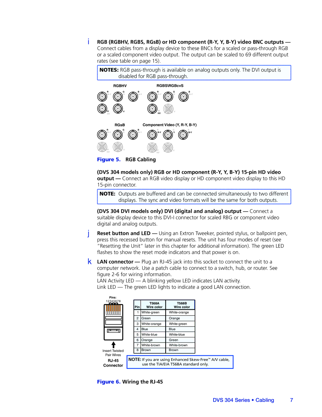
IRGB (RGBHV, RGBS, RGsB) or HD component
Connect cables from a display device to these BNCs for a scaled or
NOTES: RGB |
disabled for RGB |
RGBHVRGBS\RGBcvS
R | G | B | R | G | B |
/Y | /Y | ||||
H/ | V |
| H/ | V |
|
| HV |
| |||
HV |
|
|
|
| |
| RGsB |
| Component Video (Y, | ||
R | G | B | R | G | B |
/Y | /Y | ||||
H/ | V |
| H/ | V |
|
HV |
|
| HV |
|
|
Figure 5. RGB Cabling
(DVS 304 models only) RGB or HD component (R-Y, Y, B-Y) 15-pin HD video output — Connect an RGB video display or HD component video display to this HD 15-pin connector.
![]() NOTE: Outputs are buffered and can be connected simultaneously to two different
NOTE: Outputs are buffered and can be connected simultaneously to two different ![]()
![]() displays. The sync and video formats will be the same for both outputs.
displays. The sync and video formats will be the same for both outputs. ![]()
(DVS 304 DVI models only) DVI (digital and analog) output — Connect a suitable display device to this DVI-I connector for scaled RBG or component video digital and analog outputs.
JReset button and LED — Using an Extron Tweeker, pointed stylus, or ballpoint pen, press this recessed button for manual resets. The unit has four modes of reset (see
“Resetting the Unit” later in this chapter for additional information). The green LED flashes to show the reset mode indicators and that power is on.
KLAN connector — Plug an
LAN Activity LED — A blinking yellow LED indicates LAN activity. Link LED — The green LED lights to indicate a good LAN connection.
Pins:
12345678
Insert Twisted
Pair Wires
RJ-45
Connector
| T568A | T568B |
Pin | Wire color | Wire color |
1 | ||
|
|
|
2 | Green | Orange |
3 | ||
|
|
|
4 | Blue | Blue |
5 | ||
6 | Orange | Green |
7 | ||
|
|
|
8 | Brown | Brown |
|
|
|
NOTE: If you are using Enhanced
Figure 6. Wiring the RJ-45
DVS 304 Series • Cabling | 7 |