Quick Start Guide — IPI 101, IPI 104
WInstallation and service must be performed by authorized personnel only. These products must be used with UL approved, grounded electrical boxes.
To install an Extron IP Intercom® Sytem, follow the steps below:
Step 1
Turn all of the equipment off and disconnect the power cords.
Step 2
Select the installation location and install an electrical wall box for each IPI unit and MLC 226 IP in the system. See “Sample Applications” on page
Step 3
Install button labels in each of the IPI’s buttons. See page
Step 4
Mount each IPI into an AAP wallplate or device faceplate, as described on page
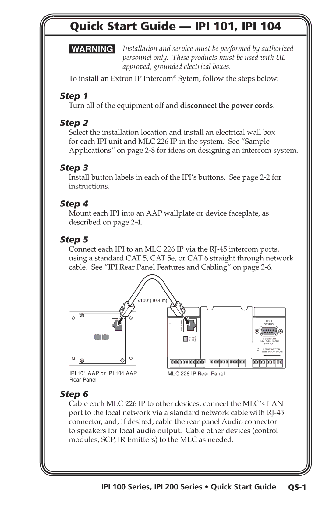
Step 5
Connect each IPI to an MLC 226 IP via the
<100’ (30.4 m)
R | INTERCOM |
| AUDIO OUT |
| HOST |
| CONTROL |
| 1=DIGITAL I/O |
| 2=Tx 3=Rx 5=GND |
| 38400, N, 8, 1 |
LAN | PRESS TAB WITH |
TWEEKER TO REMOVE |
IPI 101 AAP or IPI 104 AAP | MLC 226 IP Rear Panel |
Rear Panel |
|
Step 6
Cable each MLC 226 IP to other devices: connect the MLC’s LAN port to the local network via a standard network cable with