Installation, cont’d
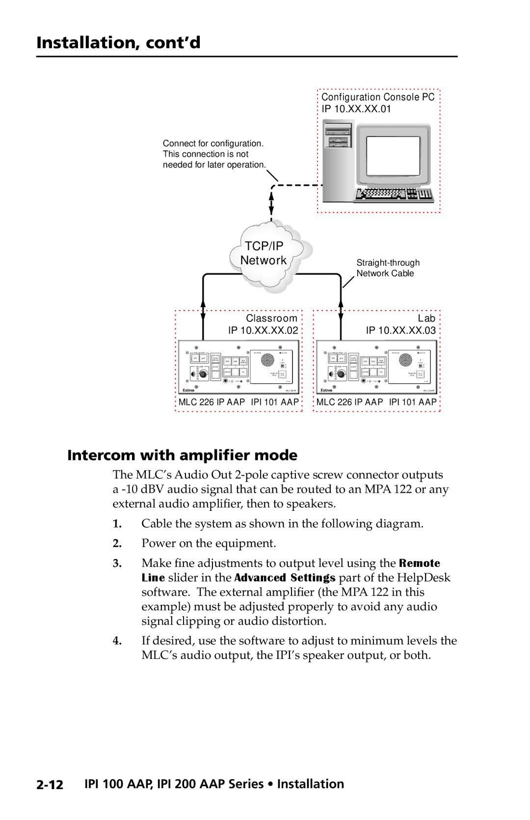
Connect for configuration. This connection is not needed for later operation.
Configuration Console PC |
IP 10.XX.XX.01 |
TCP/IP
NetworkStraight-through
Network Cable
Classroom | Lab |
IP 10.XX.XX.02 | IP 10.XX.XX.03 |
PROJECTOR |
|
|
|
| INTERCOM | MIC ON | PROJECTOR |
|
|
|
| INTERCOM | MIC ON | ||
ON | OFF | AUTO |
|
|
|
|
| ON | OFF | AUTO |
|
|
|
|
|
|
| IMAGE | VCR | DVD | AUX |
|
|
|
| IMAGE | VCR | DVD | AUX |
|
|
|
|
| VIDEO |
| LEVEL |
|
|
| VIDEO |
| LEVEL | ||||
VOLUME | MUTE |
|
|
|
|
| VOLUME | MUTE |
|
|
|
|
| ||
|
|
| LAPTOP |
| PC | PUSH TO | HELP |
|
|
| LAPTOP |
| PC | PUSH TO | HELP |
|
|
|
|
|
| TALK | DESK |
|
|
|
|
|
| TALK | DESK |
|
|
|
|
|
|
| IPI 101 |
|
|
|
|
|
|
| IPI 101 |
MLC 226 IP | MLC 226 IP |
MLC 226 IP AAP IPI 101 AAP | MLC 226 IP AAP IPI 101 AAP |
Intercom with amplifier mode
The MLC’s Audio Out
1.Cable the system as shown in the following diagram.
2.Power on the equipment.
3.Make fine adjustments to output level using the Remote Line slider in the Advanced Settings part of the HelpDesk software. The external amplifier (the MPA 122 in this example) must be adjusted properly to avoid any audio signal clipping or audio distortion.
4.If desired, use the software to adjust to minimum levels the MLC’s audio output, the IPI’s speaker output, or both.