Hydra
Limited Warranty & Limitation of Liability
Interference Information
Page
Safety Summary
Do Not Operate in Explosive Atmospheres
Table of Contents
Hydra
General Maintenance
Performance Testing and Calibration
Diagnostic Testing and Troubleshooting 2635A 5A-1
Schematic Diagrams Hydra Starter Calibration Software
List of Tables
5A-19
List of Figures
5A-10
Introduction and Specifications
Hydra
Operating Instructions
Options and Accessories
Introduction
Theory of Operation 2635A
IEEE-488 Option 2620A only Schematic Diagrams
Conventions
Hydra Features
Model
Specifications
Accessories Description
Normal Mode Rejection
A/2625A Specifications
DC Voltage Inputs Resolution Range
Common Mode Rejection
100.00
Wire Accuracy
A/2625A Specifications Thermocouple Inputs Input Impedance
Common Mode and Normal Mode Rejection
Maximum Open Circuit Voltage Maximum Sensor Temperature
0C to 60C Slow Fast
Using Channel
Crest Factor Error Input at Upper Frequency
DC Component Error
Maximum Crest Factor
Typical Full Maximum Current Scale Voltage Through Unknown
A/2625A Specifications Ohms Input Range
Resolution Slow Fast
Input Protection
Slow Fast
Typical Scanning Rate
Function Range Channels
Trigger Inputs
Totalizing Inputs
Digital Inputs
Environmental
A/2625A Specifications Digital and Alarm Outputs
Real-Time Clock and Calendar
General
RS-232-C
2625A Data Storage
AC Signal Crosstalk into an AC Voltage Channel
A/2625A Specifications 2620A Options IEEE-488 Option -05K
AC Signal Crosstalk in a DC Voltage Channel
Typical
AC Signal Crosstalk into a Temperature Channel
Type Worst case Typical
A Specifications
DC Voltage Inputs Resolution Range Slow Fast
A Specifications Input Impedance
Days Slow Year Slow Year Fast
Introduction and Specifications
A Specifications Thermocouple Inputs Input Impedance
300 mV 10 μV 100 μV 30V 10 mV 150/300V 100 mV
Maximum Crest Factor
A Specifications Ohms Input Range
Typical Scanning Rate Function Range Channels
Totalizing Inputs
A Specifications Digital and Alarm Outputs
TX, RX, DTR, DSR, RTS, CTS, GND
Hydra
Theory of Operation 2620A/2625A
Totalizer Input External Trigger Input Circuits
Introduction
Interconnect Diagram
Theory of Operation 2620A/2625A Functional Block Description
A/D Converter PCA
Detailed Circuit Description
Power Supply Circuit Description
Inverter
Power Fail Detection
Microprocessor Memory Map Hexadecimal Address
Device Selected
Display/Keyboard Interface
Eeprom
Digital I/O
Digital Input Threshold
49. A/D Converter PCA
Input Protection
Analog
Simplified
Pin Name
Analog Measurement Processor Pin Descriptions
Function Relays
Analog Measurement Processor Pin Descriptions Name
A3K15
Function Relay States Relay Position A3K17
A3K16
Input HI
Ohms Simplified Schematic
AC Volts
A3Z3 Divider Resistors
AC Volts Input Signal Dividers Range
Drive Signal
Overall Gain
59. A/D Converter
Inguard Microcontroller Circuitry
Input Connector PCA
Main PCA Connector
Display
Display Controller
Power-Up Display Initialization
Display Initialization Modes
Address Decoding
IEEE-488 Interface Option
Theory of Operation 2635A
2A-49
2A-2. Functional Block Description
2A-4. Power Supply
2A-1. Introduction
2A-3. Main PCA Circuitry
2A-4
Functional Block Description
2A-8. A/D Converter PCA
2A-19. Display PCA
2A-16. Input Connector Assembly
2A-21. Detailed Circuit Description
2A-20. Memory Card Interface PCA
2A-23.Power Supply Circuit Description
2A-24.Raw DC Supply
2A-27.Inverter
2A-29.Inverter Inguard Supply
2A-31.Digital Kernel
2A-33.Microprocessor
Signal Name
1. Microprocessor Interrupt Sources 2635A Pin
2A-34.Address Decoding
2A-35.Flash Eprom
2A-37.Serial Communication Guard Crossing
2A-38.Display/Keyboard Interface
Clock Dividers
2A-40.RS-232 Interface
2A-43.Digital Input Threshold
2A-45.Digital and Alarm Output Drivers
2A-42.Digital I/O
2A-44.Digital Input Buffers
2A-49.Analog Measurement Processor
2A-47.External Trigger Input Circuits
2A-48. A/D Converter PCA
2A-21
2A-22
2A-23
2A-50.Input Protection
4. Analog Measurement Processor Pin Descriptions 2635A Name
2A-51.Input Signal Conditioning
5. Function Relay States 2635A Relay Position A3K17
2A-54.Ohms and RTDs
2A-27
2A-55.AC Volts
6. AC Buffer Simplified Schematic 2635A
6. AC Volts Input Signal Dividers 2635A Range
2A-57.Passive and Active Filters
2A-58.A/D Converter
2A-31
2A-61.Open Thermocouple Check
2A-59.Inguard Microcontroller Circuitry
2A-60.Channel Selection Circuitry
Power Supply A2J1 Pins Nominal Voltage
2A-62. Input Connector PCA
2A-64.Main PCA Connector
2A-63. Display PCA
2A-67.Beeper Drive Circuit
2A-65.Front Panel Switches
2A-66.Display
2A-68.Watchdog Timer and Reset Circuit
2A-69.Display Controller
8. Display Initialization Modes 2635A
9. Grid Control Signal Timing 2635A
2A-70. Memory Card Interface PCA
2A-73.Memory Card Controller
2A-71.Main PCA Connector
2A-72.Microprocessor Interface
2A-74.PCMCIA Memory Card Connector
2A-40
Static awareness
Dow Chemical
General Maintenance
Install the Handle and Mounting Brackets
Power Requirements
Warranty Repairs and Shipping
General Maintenance
Required Equipment
Cleaning
Servicing Surface-Mount Assemblies
Line Fuse Replacement
Disassembly Procedures
Remove Handle and Mounting Brackets
Remove the Front Panel Assembly
Remove the Instrument Case
Remove the Display PCA
Disassembly Procedures
Removing the Handle and Handle Mounting Brackets
A and 2625A Assembly Details
A Assembly Details
Remove the Memory Card I/F PCA 2635A Only
Remove the IEEE-488 Option 2620A Only
Remove the Memory PCA 2625A Only
Remove the Main PCA
Remove the A/D Converter PCA
Install the A/D Converter PCA
Assembly Procedures
Install Miscellaneous Chassis Components
Disconnect Miscellaneous Chassis Components
Install the Memory PCA 2625A Only
Install the Main PCA
Install the IEEE-488 Option 2620A Only
Install the Front Panel Assembly
Install the Memory Card I/F PCA 2635A Only
Assemble the Front Panel Assembly
Install the Handle and Mounting Brackets
Hydra
Performance Testing and Calibration
Hydra
Instrument Type
Recommended Test Equipment Minimum Specifications
Introduction Required Equipment
Recommended Model
Channel Integrity Test
Performance Tests
Accuracy Verification Test
Performance Tests Voltage, Resistance, and Frequency
Year, 18-28C
Thermocouple Measurement Range Accuracy Test
Function Range Input Level
Terminal Resistance Test
Func 0,VDC,I100MV CR MON 1,0 CR MONVAL? CR
Thermocouple Temperature Accuracy Test
Input Module
11 12 13 14 15 16 17 18 19
11 12 13 14 15 16 17 18 19 3 4 5 6 7 8 9
Negative Lead Material
Thermocouple Information Type Positive Lead Material
Positive Lead Color
Usable Range
RTD Temperature Accuracy Test
Open Thermocouple Response Test
Temperature Accuracy Specifications Year @ 18-28C
RTD Temperature Accuracy Test Using DIN/IEC
Simulated C Temperature 2620A/2635A
Digital Input/Output Verification Tests
Digital Output Test
Terminal Grounded
Digital Input Test
Totalizer Test
Digital Input Values State of Digital Inputs
Totalizer Sensitivity Test
Dedicated Alarm Output Test
2 3 4 5 6 7 Σ + 0 1 2 3 TR
5700A
Calibration
External Trigger Input Test
Performance Testing and Calibration
Command
Using Hydra Starter Calibration Software
Setup Procedure Using Starter
Calibration Mode Computer Interface Commands Description
Calibration Procedure Using Starter
Calibration Procedure Using a Terminal
Using a Terminal
Setup Procedure Using a Terminal
Response
DC Volts Calibration Action
Reference Junction Calibration
10. AC Volts Calibration Action
Concluding Calibration
Terminal Connections to Decade Resistance Source
Hydra Input Module
11 -Wire Ohms Calibration Fixed Resistor Command
Updating 2635A Data Bucket Embedded Instrument Firmware
Using the PC Compatible Firmware Loader Software
12 -Wire Ohms Calibration 5700A Command
13. Frequency Calibration Command
Setup Procedure for Firmware Download
Default Instrument Firmware Download Procedure
Using LD2635 Firmware Loader Directly
Diagnostic Testing and Troubleshooting 2620A/2625A
Failure to Detect Memory PCA Failure to Store Data
Servicing Surface-Mount Assemblies
Error Codes
Each error code is displayed for 2 seconds
Error Error Codes Description
General Troubleshooting Procedures
Preregulated Power Supplies
Test Point Locator, Main PCA A1
Volt Switching Supply
Power Supply Troubleshooting
Power Fail Detection
Raw DC Supply
Volt Switching Supply
Inverter
Hydra
FET Gate Signal
Analog Troubleshooting
Power Supply Test Location Acceptable Range
Power Supply Troubleshooting Guide Symptom
Fault
Test Point Pulses
Test Points, A/D Converter PCA A3, A3U9
A3U9
Microcontroller
DC Volts HI Troubleshooting Checkpoint
DC Volts Troubleshooting
AC Volts Troubleshooting
Signal Description
Ohms HI Troubleshooting Checkpoint
Ohms Troubleshooting
AC Volts HI Troubleshooting Checkpoint
Ohms Open-Circuit Voltage Range
Digital Kernel Troubleshooting
Microprocessor Timing
Totalizer Troubleshooting
Digital and Alarm Output Troubleshooting
Digital Input Troubleshooting
Test Points, Display PCA A2
Display Assembly Troubleshooting
Review
Variations in the Display
Calibration-Related Components
Calibration Failures
Introduction
AC Volts 1 kHz
Ohms
Retrieving Calibration Constants
Replacing the Eeprom A1U1
Power-Up Problems
IEEE-488 Interface PCA A5 Troubleshooting
Memory PCA A6 Troubleshooting
Failure to Detect Memory PCA
Hydra
Diagnostic Testing and Troubleshooting 2635A
Failure to Detect Insertion of Memory Card
5A-1. Introduction
5A-2. Servicing Surface-Mount Assemblies
5A-3. Error Codes
Error
1. Error Codes 2635A Description
2. Preregulated Power Supplies 2635A Preregulated Voltage
5A-4. General Troubleshooting Procedures
1. Error Codes 2635A
Measurement Points
General Troubleshooting Procedures
5A-8 -Volt Switching Supply
5A-5. Power Supply Troubleshooting
5A-7. Power Fail Detection
5A-6. Raw DC Supply
2 -Volt Switching Supply 2635A
5A-9. Inverter
5A-10
5A-10. Analog Troubleshooting
3. Power Supply Troubleshooting Guide 2635A Symptom
Power Supply Nearest Component Acceptable Range
5A-14
5A-15
5A-11. DC Volts Troubleshooting
6. Integrator Output 2635A
4. DC Volts HI Troubleshooting 2635A Checkpoint
5A-12. AC Volts Troubleshooting
5A-13. Ohms Troubleshooting
5. AC Volts HI Troubleshooting 2635A Checkpoint
6. Ohms Open-Circuit Voltage 2635A Range
5A-14. Digital Kernel Troubleshooting
Voltage 7. Ohms HI Troubleshooting 2635A Checkpoint
Output A12 A11 A10
5A-20
5A-15. Digital and Alarm Output Troubleshooting
5A-16. Digital Input Troubleshooting
5A-22
5A-17. Totalizer Troubleshooting
5A-18. Display Assembly Troubleshooting
5A-24
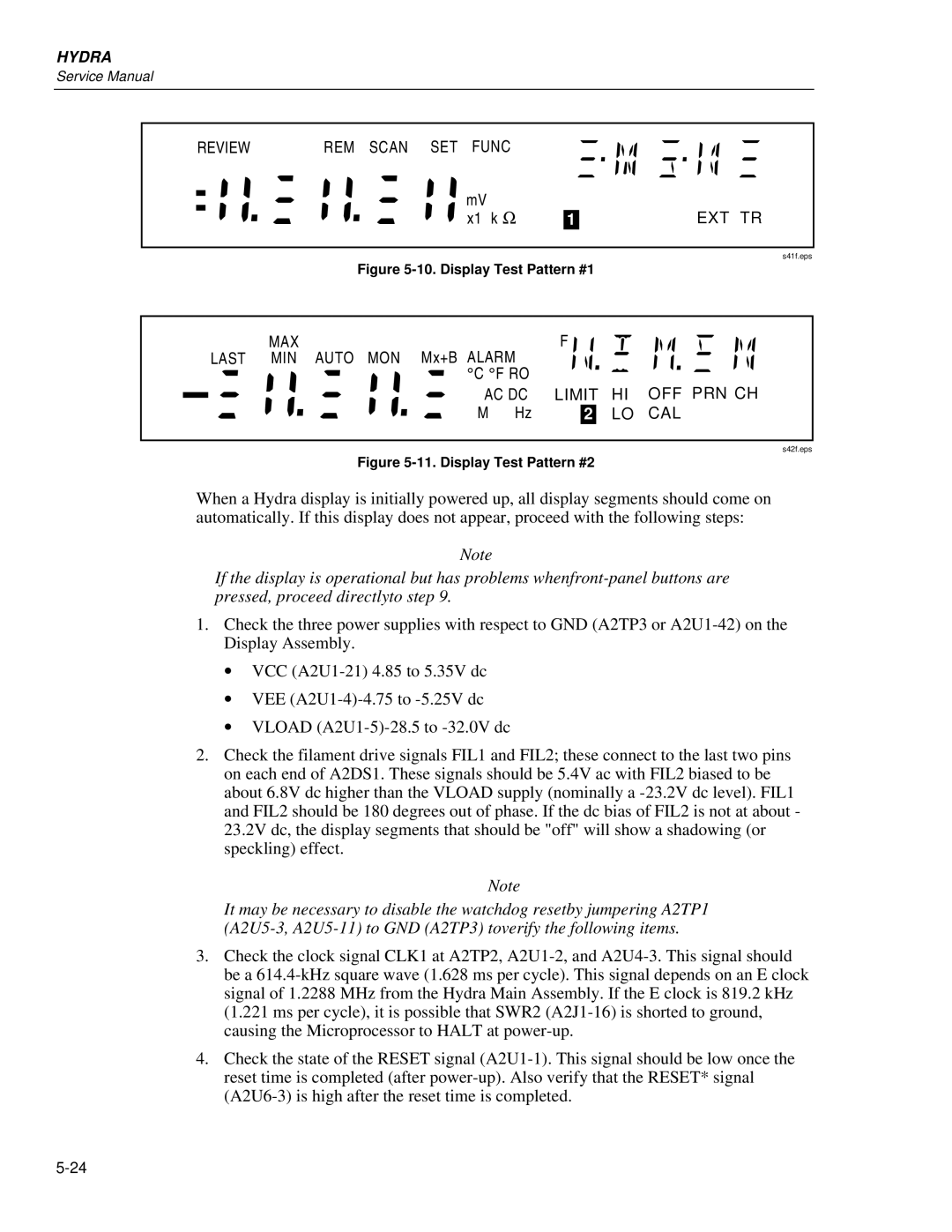
9. Display Controller to Microprocessor Signals 2635A
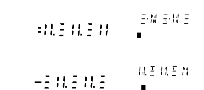
10. Display Test Pattern #1 2635A
5A-19. Variations in the Display
5A-22. Calibration-Related Components
5A-20. Calibration Failures
5A-21. Introduction
5A-28
5A-23. Retrieving Calibration Constants
5A-24. Replacing the Flash Memory A1U14 and A1U16
5A-27. Failure to Detect Memory Card I/F PCA
5A-25. Memory Card I/F PCA A6 Troubleshooting
5A-26. Power-Up Problems
Battery LED
5A-29. Failure to Power Card / Illuminate the Busy Led
5A-30. Failure to Illuminate the Battery Led
5A-28. Failure to Detect Insertion of Memory Card
5A-31. Failure to Write to Memory Card
5A-32. Write/Read Memory Card Test Destructive
Memory card test passed without detecting any errors
5A-34
List of Replaceable Parts
Hydra
How to Obtain Parts
Manual Status Information
Revision
Service Centers
Newer Instruments
List of Replaceable Parts Service Centers
A/2625A Final Assembly
TM1 TM2 TM3 TM4 TM5 TM6
2620A/2625A T&B
Bottom View
Top View
S58f.eps
A Final Assembly
TM1 TM2 TM3 TM4 TM5
2635A T&B
Part of W2 MP102 H52 Cable Assembly
T1 Ref H52
S62f.eps
A/2625A A1 Main PCA
CR5,CR6
Reference Description Designator
VR1 VR2 VR3 VR4
2620A-1601
A A1 Main PCA
CAP,AL,10UF,+-20%,63V,SOLV Prooof
MP101 Q1-3,Q10 Q4-6 Q7,Q8 R1,R11,R12 R22,R25,R45
INDUCTOR,FXD,DUAL,EE24-25,0.4MH,1.2A
2635A-1601
WIRE,JUMPER,TEF,22AWG,WHT,.300
A2 Display PCA
CKT
A3 A/D Converter PCA
Reference Description Designator Fluke Stock Tot Qty
Reference Description Fluke Stock Designator
K3, K5-K14 Relay Polarity
A4 Analog Input PCA
Reference Description Fluke Stock Tot Qty Designator
2620A-1604
A5 Option -05 IEEE-488 Interface PCA
A5 IEEE-488 Interface PCA Option
A A6 Memory PCA
2625A-1606
10 a A6 Memory Card I/F PCA
2635A-1606
Hydra
IEEE-488 Option
Hydra
Functional Block Description
Theory of Operation
IEEE-488 PCA Detailed Circuit Description 2620A Only
Main PCA Connector
IEEE-488 Controller
IEEE-488 Transceiver Control
IEEE-488 Transceivers/Connector
Removing the IEEE-488 Option
Installation
Performance Testing
Installing the IEEE-488 Option
Failure to Select IEEE-488 Option
Troubleshooting
Communication Problems
Failure to Handshake on IEEE-488 Bus
Schematic Diagram
List of Replaceable Parts
Hydra
Schematic Diagrams
Hydra
Schematic Diagrams
Power Supply PIN Numbers DES
RAW Supply
2620A-1001
U S E D
Reference Designations Lasted Used Not Used
A1 Main PCA 2635A
2635A-1001
2635A-1001
2635A-1001
Control
External Trigger Totalizer Inputs
CKT
2620A-1002
S91c.eps
2620A-1003
S82c.eps
S83c.eps
S92f.eps
2620A-1004
A5 IEEE-488 Interface PCA 2620A Only
1V dc
A6 Memory PCA 2625A
A6U1 A6U2 A6U3 A6U4 A6U5 A6U6 A6U7 A6U8 2625A-1006
Reference Designations
Lasted Used Not Used 0V dc
2635A-1006
Schematic Diagrams