Installation Requirements
3.2.4 Precautions on mounting
(1)Mounting frame structure and clearance
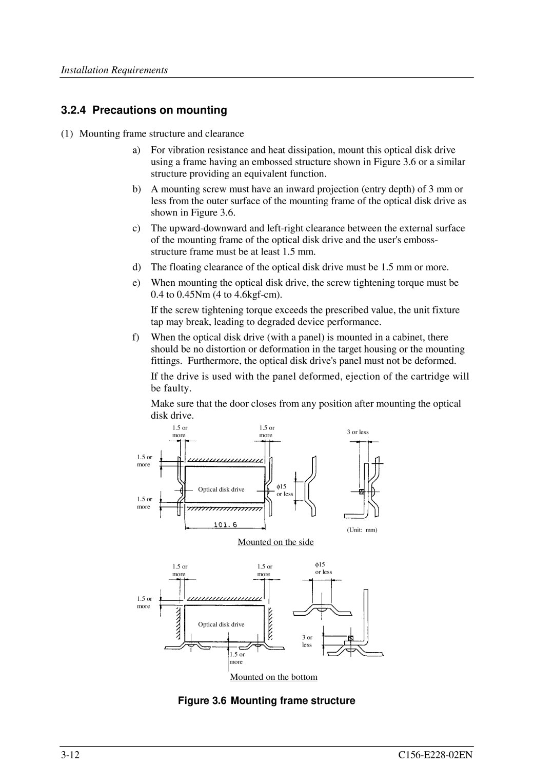
a)For vibration resistance and heat dissipation, mount this optical disk drive using a frame having an embossed structure shown in Figure 3.6 or a similar structure providing an equivalent function.
b)A mounting screw must have an inward projection (entry depth) of 3 mm or less from the outer surface of the mounting frame of the optical disk drive as shown in Figure 3.6.
c)The
d)The floating clearance of the optical disk drive must be 1.5 mm or more.
e)When mounting the optical disk drive, the screw tightening torque must be 0.4 to 0.45Nm (4 to
If the screw tightening torque exceeds the prescribed value, the unit fixture tap may break, leading to degraded device performance.
f)When the optical disk drive (with a panel) is mounted in a cabinet, there should be no distortion or deformation in the target housing or the mounting fittings. Furthermore, the optical disk drive's panel must not be deformed.
If the drive is used with the panel deformed, ejection of the cartridge will be faulty.
Make sure that the door closes from any position after mounting the optical
disk drive.
1.5 or | 1.5 or | 3 or less | |
more | more | ||
|
1.5or more
Optical disk drive | φ 15 | |
or less | ||
|
1.5or more
(Unit: mm)
| Mounted on the side |
|
| |
|
|
|
| |
1.5 or | 1.5 or | φ 15 | ||
or less | ||||
more | more | |||
|
| |||
1.5or more
Optical disk drive
3 or less
1.5or more
Mounted on the bottom