3.4 Connection Requirement
Provide switches and LEDs (required for the system) on the external operator panel. See the recommended circuit shown in Figure 3.21. A signal which is not set on the external operator panel connected to CNH2 must be set using SW1. The SW1, and CNH1 corresponding to the signal set on the external operator panel must be set to OFF position.
For details, see Subsection 4.3.1.
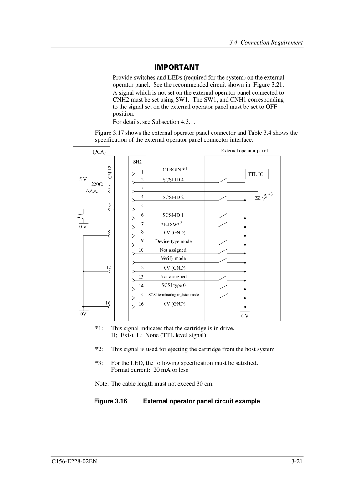
Figure 3.17 shows the external operator panel connector and Table 3.4 shows the specification of the external operator panel connector interface.
Not assigned
Not assigned
SCSI terminating register mode
*1: This signal indicates that the cartridge is in drive. H; Exist L: None (TTL level signal)
*2: This signal is used for ejecting the cartridge from the host system
*3: For the LED, the following specification must be satisfied. Format current: 20 mA or less
Note: The cable length must not exceed 30 cm.