Installation Requirements
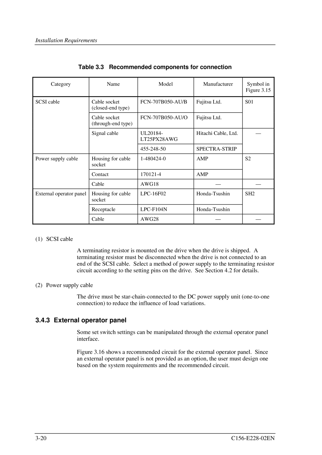
Table 3.3 Recommended components for connection
Category | Name | Model | Manufacturer | Symbol in |
|
|
|
| Figure 3.15 |
|
|
|
|
|
SCSI cable | Cable socket | Fujitsu Ltd. | S01 | |
|
|
|
| |
|
|
|
|
|
| Cable socket | Fujitsu Ltd. |
| |
|
|
|
| |
|
|
|
|
|
| Signal cable | UL20184- | Hitachi Cable, Ltd. | — |
|
| LT25PX28AWG |
|
|
|
|
|
|
|
|
|
| ||
|
|
|
|
|
Power supply cable | Housing for cable | AMP | S2 | |
| socket |
|
|
|
|
|
|
|
|
| Contact | AMP |
| |
|
|
|
|
|
| Cable | AWG18 | — | — |
|
|
|
|
|
External operator panel | Housing for cable | SH2 | ||
| socket |
|
|
|
|
|
|
|
|
| Receptacle |
| ||
|
|
|
|
|
| Cable | AWG28 | — | — |
|
|
|
|
|
(1) SCSI cable
A terminating resistor is mounted on the drive when the drive is shipped. A terminating resistor must be disconnected when the drive is not connected to an end of the SCSI cable. Select a method of power supply to the terminating resistor circuit according to the setting pins on the drive. See Section 4.2 for details.
(2) Power supply cable
The drive must be
3.4.3 External operator panel
Some set switch settings can be manipulated through the external operator panel interface.
Figure 3.16 shows a recommended circuit for the external operator panel. Since an external operator panel is not provided as an option, the user must design one based on the system requirements and the recommended circuit.
|
