F |
Application #1: FLIP / FLOP (Toggle Operation)
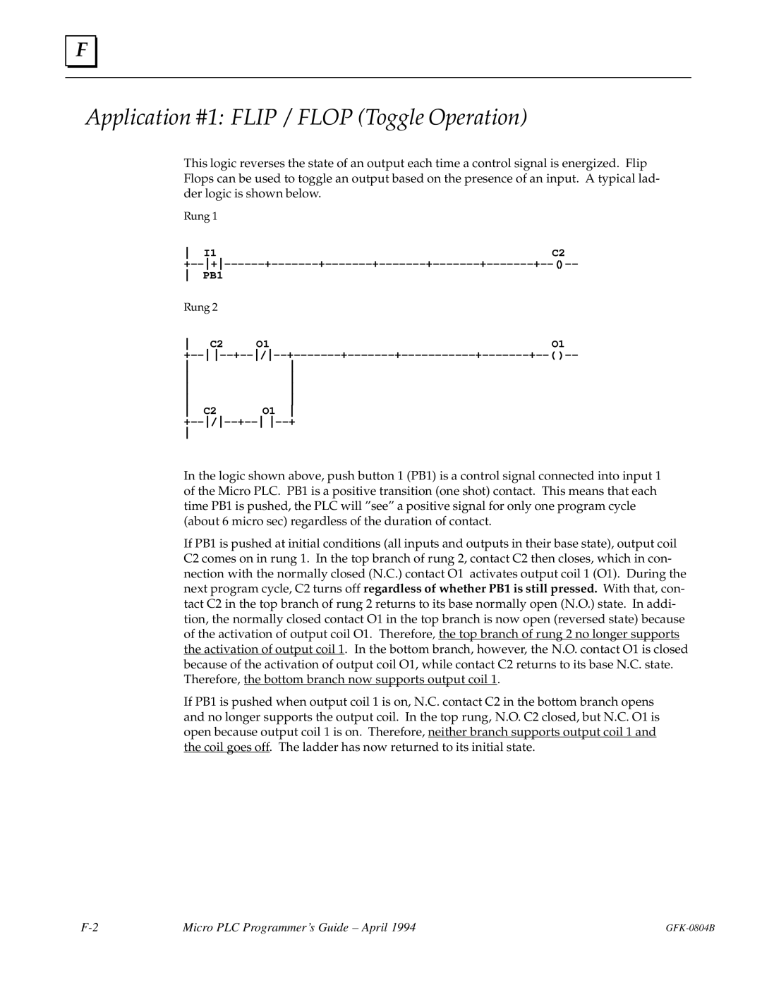
This logic reverses the state of an output each time a control signal is energized. Flip Flops can be used to toggle an output based on the presence of an input. A typical lad- der logic is shown below.
Rung 1 |
|
I1 | C2 |
+±±+±±±±±±+±±±±±±±+±±±±±±±+±±±±±±±+±±±±±±±+±±±±±±±+±±()±±
PB1 |
|
| |
Rung 2 |
|
| |
C2 | O1 | O1 | |
+±± ±±+±±/±±+±±±±±±±+±±±±±±±+±±±±±±±±±±±+±±±±±±±+±±( )±±
C2 | O1 |
+±±/±±+±± ±±+
In the logic shown above, push button 1 (PB1) is a control signal connected into input 1 of the Micro PLC. PB1 is a positive transition (one shot) contact. This means that each time PB1 is pushed, the PLC will ºseeº a positive signal for only one program cycle (about 6 micro sec) regardless of the duration of contact.
If PB1 is pushed at initial conditions (all inputs and outputs in their base state), output coil C2 comes on in rung 1. In the top branch of rung 2, contact C2 then closes, which in con- nection with the normally closed (N.C.) contact O1 activates output coil 1 (O1). During the next program cycle, C2 turns off regardless of whether PB1 is still pressed. With that, con- tact C2 in the top branch of rung 2 returns to its base normally open (N.O.) state. In addi- tion, the normally closed contact O1 in the top branch is now open (reversed state) because of the activation of output coil O1. Therefore, the top branch of rung 2 no longer supports the activation of output coil 1. In the bottom branch, however, the N.O. contact O1 is closed because of the activation of output coil O1, while contact C2 returns to its base N.C. state. Therefore, the bottom branch now supports output coil 1.
If PB1 is pushed when output coil 1 is on, N.C. contact C2 in the bottom branch opens and no longer supports the output coil. In the top rung, N.O. C2 closed, but N.C. O1 is open because output coil 1 is on. Therefore, neither branch supports output coil 1 and the coil goes off. The ladder has now returned to its initial state.
Micro PLC Programmer's Guide ± April 1994 |