4 |
Timers
The Micro PLC instruction set provides two Timers:
On Timer Sets an output to 1 after a specified time period. See page
Off Timer Sets an output to 0 after a specified time period. See page
Programming Software Instructions for Timers
Timers require input logic in the same rung. This can be entered either before selecting the Timer function, or after as described below. Note that the enable line for a timer CANNOT contain parallel branches or instructions. If this type is logic is desired, place it in another rung, using it to drive an internal coil which then drives the timer.
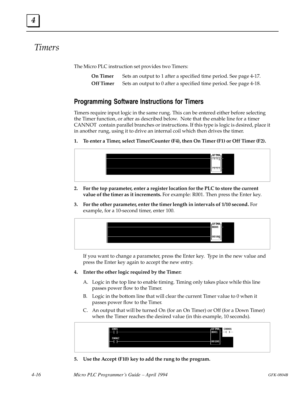
1.To enter a Timer, select Timer/Counter (F4), then On Timer (F1) or Off Timer (F2).
2.For the top parameter, enter a register location for the PLC to store the current value of the timer as it increments. For example: R001. Then press the Enter key.
3.For the other parameter, enter the timer length in intervals of 1/10 second. For example, for a
If you want to change a parameter, press the Enter key. Type in the new value and press the Enter key again to accept the new entry.
4.Enter the other logic required by the Timer:
A.Logic in the top line to enable timing. Timing only takes place while this line passes power flow to the Timer.
B.Logic in the bottom line that will clear the current Timer value to 0 when it passes power flow to the Timer.
C.An output that will be turned On (for an On Timer) or Off (for a Down Timer) when the Timer reaches the desired value (in this example, 10 seconds).
5.Use the Accept (F10) key to add the rung to the program.
Micro PLC Programmer's Guide ± April 1994 |