GE Fanuc Automation
GFL±002
Related Publications
Content of this Manual
We Welcome Your Comments and Suggestions
Preface
Technical Assistance
Contents
Math Functions
Appendix a Using Directories Appendix B Micro PLC Protocol
Appendix E Data Acquisition, Logging, and Display Program
Chapter Programming for the Micro PLC
Device Designation
Programming Basics
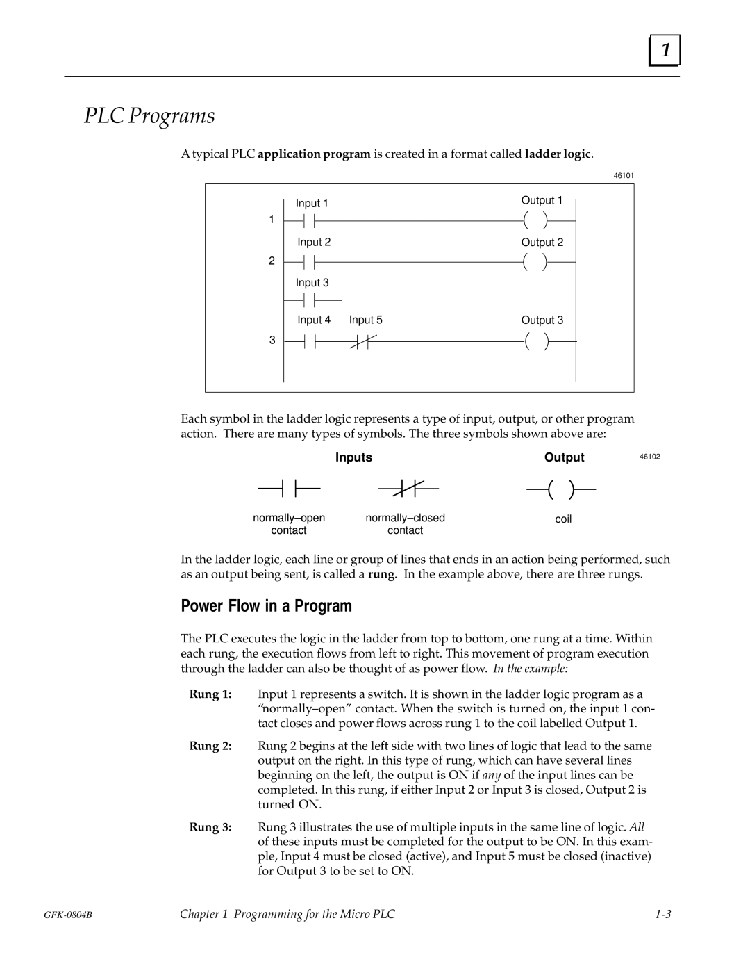
PLC Programs
Power Flow in a Program
Micro PLC Instruction Set
Programming on a Hand-held Programmer
Programming Devices and Formats
Programming with the Programming Software
Non-retentive and Retentive Registers
Memory Types and Addresses
Constants and Register Values in a Program
Memor y Map
Hold Output Coil C1021
Special Coils
Sec Clock C1018
Start-up Scan Coil C1019
Maximum Values
Programming for an Analog Expander Unit
Analog Scaling
Analog References
Example #1
Programming Examples
Chapter Programming with the Programming Software
Programming Operations
Using the Programming Functions
Programming Functions
Creating a Program Rung
Running the Programming Software Directly from a Diskette
Running the Programming Software
Running the Programming Software from a Hard Disk
Editing Basics
Horizontal and Vertical Lines in a Rung
Element Labels and Rung Labels
Deleting a Rung Element
Editing a Completed Rung
Selecting a Rung to Edit
Editing a Rung Element
Adding a Program Function to a Rung
Adding a Contact to a Rung
Replacing a Rung Element with a Horizontal Line
Replacing a Rung Element with a Similar Element
Replacing a Rung Element with a Dissimilar Element
Moving Rungs
Deleting Rungs
Copying Rungs
Searching for a Rung or Program Element
Chapter Programming with a Hand-held Programmer
Program Transfer
Program Listing
Hand-Held Programmer Key Operation and Displays
Entering Program Logic
Inserting a Rung Element
Deleting a Rung Element, Rung or Program In Memory
Deleting a Rung Element
Searching
Programming Examples Using the HHP
Ladder Diagram
Chapter Micro PLC Instruction Set
Instruction Set Summary
Operation Ladder Symbol Description
Micro PLC Instruction Set
General Programming Software Instructions for Contacts
Contacts
Programming Normally-Open Contact at the Start of a Rung
Normally- Open Contact
Programming Software Instructions
Examples and HHP Instructions
Programming a Normally-Open Contact in Parallel
Programming a Normally-Open Contact in Series
Programming Normally-Closed Contact at the Start of a Rung
Normally- Closed Contact
Programming a Normally-Closed Contact in Parallel
Programming a Normally-Closed Contact in Series
Example and HHP Instructions
Positive Transition Contact
Example and HHP Instructions
Negative Transition Contact
General Programming Software Instructions for Coils
Using Coil Pairs
Coils
Output Coil
Example and HHP Instructions Set
Set/Reset Coil Pair
Reset
End
Master Control Relay/End Coil Pair
Skip
Skip/End Coil Pair
Use the Accept F10 key to add the rung to the program
Timers
Programming Software Instructions for Timers
Enter the other logic required by the Timer
On Timer
Off Timer
Enter the other logic required by the Counter
Counters
Programming Software Instructions for Counters
Up Counter
Down Counter
Addition
Math Functions
Addition ADD
Maximum Total
R1+R2 ! R3 R1+ 1! R4
1st number 2nd number Total in register
Subtraction SUB
R1± 5! R2 R3±R4 ! R5
Examples
Multiplication MUL
R1 x R2! R3
Whole # Remainder
Division DIV
Divide
Using Division and Multiplication Functions Together
Select Move F5 from the Math/Move function keys
Move Functions
Move
Move
Ladder Diagram Hand-held Programmer
R001 0002 R004 R010 R020 R100
Block Move
R1E 5! R10 O9E 8! O17
Select I±Move F7 from the Math/Move function keys
Indirect Move
Specifying a Location in the Pointer Register
Start Move
Greater
Compare Functions
Examples
Equal
Press Enter to add the function to the program
Not
Logic Operations
Word
Inclusive or IOR
Exclusive or XOR
Entering the Number of Positions to Shift
Shift Register Right
Shift Register Left
Not
Loading and Saving Files
Appendix Using Directories
Hints for a Basic Application
Using the Change Directory Function
MICRO.CFG File
CMD\MICRO\PALLET CMD\MICRO\RIVETER CMD\MICRO\TRANSFER
Hints for an Advanced Application
Appendix Micro PLC Protocol
Communications Files
Special Registers
Communications Memory Types and Addresses
Communications Parameters
Memory Addresses
Reply
Communications Protocol
Data Format
Read Discretes
Write Analogs
Read Analogs
Read Program Memory
Write Discretes
Status Word
Write Program Memory
Read Status
Stop Program
Error Reply
Error codes
Start Program
Microsoft C Large Model Compile w/ -AL Option
Communications Functions
Microsoft C Small Model Compile w/ -AS Option
Turbo C Large Model Compile w/ -ml Option
Turbo C Small Model Compile w/ -ms Option
IBM Compiler Basic
#include dos.h #include stdio.h #include ªMCROCOMM.Cº
Sample Programs
Sample Basic Program
Introduction
Appendix RTU Protocol
Broadcast
Message Types
Transmission Sequence
Query
Function Code
Error Check Field
Message Fields
Station Address
Message Termination
Timeout Usage
Character Format
Generating Polynomial
Cyclic Redundancy Check CRC
Software Calculation of CRC±16
Hardware Implementation of CRC-16
Address Function CRC±16
Example CRC±16 Calculation
Response Message Length Less CRC Code
RTU Message Length
Function Code And Name
Query or Broadcast Message Length Less CRC Code
Response
Message Descriptions
Message 01 Read Output Table Format
Message 02 Read Input Table Format
Message 03 Read Registers Format
Message 04 Read Analog Inputs Format
Message 05 Force Single Output Format
Message 06 Preset Single Register Format
Message 07 Read Exception Status Format
Message 16 Preset Multiple Registers Format
Message 17 Report Device Type Format
Invalid Query Message
Communication Errors
Invalid Function Code Error Response
Invalid Address Error Response
Invalid Transactions
Invalid Data Value Error Response
Query Processing Failure Error Response
Serial Link Timeout
Limits of the Demonstration Software
Appendix Communications Using Windows DDE
Features of the Micro PLC DDE Driver Software
Demonstration using Microsoft Excel
Simple Demonstration using Microsoft Word
Viewing PLC Data in Windows
Ordering Information
Viewing PLC Data in another DDE-compliant Application
Writing Values to the PLC from another Application
Using the Display Software with Micro PLC Net
Features
Overview
Appendix E Data Acquisition, Logging, and Display Program
Equipment Required
Invoking Display
Startup
Auto Polling Operation
Display Software Menus
Changing the Screen Colors
Editing Summary
Data Format
Manual Mode
Reading Multiple Bytes of Input, Output, or Register Data
Entering Manual Mode
Reading One Word of Input, Output, or Register Data
Creating a Bank of Registers for Downloading Data
15,T,1
Writing Data to the Registers
Specifying an Existing File to Edit
Creating or Editing Autopolling Screens
Naming an Auto-polling Screen File
Creating an Auto-polling Screen
Text for Auto-polling Screens
Setup for Data Logging During Auto-Polling
Formatting Strings for Auto-polling Screens
Example
Data Display String Format ± &XYYYYYZN
Format
Hilimit
Data Limits Format ± &L,X,YYYYY,LowLimit,Hilimit
#,SC,BC,LT
Colors/logtime setup format ± &#,SC,BC,LT
Creating or Editing System Messages
System Messages
Specifying the Device to Control System Message Display
Executing an Auto-polling Screen
Auto-Polling During System Operation
Forcing an Output
Changing the Display
Printing the Screen
Writing a Value to a Register
Renaming the .LOG File to Prevent Overwriting Data
Data Logging
How Data Logging Works
.LOG File
Target ID
Format of Logged Data
Time Stamp Year, Month, Day, Hour, Minutes, Seconds
Data Type Table, Reference, Data Value
Error Writing to Device COM1
Error Messages During Operation
Appendix ProgrammingApplications
Application #1 Flip / Flop Toggle Operation
Application #2 Power Up One Shot Start±up Protection
Application #3 Cascading Counters
Application #4 Industrial ªStarting Circuitº
+±± ±±+±±/±±+±±±±±±±±±±+±±±±±±±+±±±±±±±+±± ±±
Index
Index-2
Index-3