4 |
Down Counter
The Down Counter turns on an output when the count reaches zero (from 65535 to 0 if a register is used to load the counter, or 32767 to 0 if a constant is used). To program a counter function, enter two inputs (in the example below, I1, and I2), and two parameters (R2 and R386 in the example).
The first input decrements the count value. In this example, each time the Positive Transition contact transitions on, the count total stored in R1 goes down by 1. The second input to the counter resets the count total (here, in R1) to its maximum value. It also deactivates the output coil.
The first parameter of the Down Counter is a register containing the value that is being incremented (usually, by an input in the application program). Register R1, used in this example, is not a ªretentiveº register; it is cleared if power goes off. If the current count value should be saved with the power off, use a register from R385 to R500.
The second counter parameter is the counter total. If this number should always be the same, you can enter it directly, as shown in the example Up Counter. Or, if you want to be able to change the counter total, instead enter a register from R385 to R500 as the second parameter for the counter (see the example). The counter total can then be placed in that register, either by program logic, or from the
When the program encounters a register location as the second parameter of the timer, it looks in that register for the value it contains, and uses that value as the timer length. So for this example, timing is the same as for the previous example.
Programming Software Instructions
If you are using the programming software, refer to the instructions on page
Example and HHP Instructions
46129
I1
"
I2
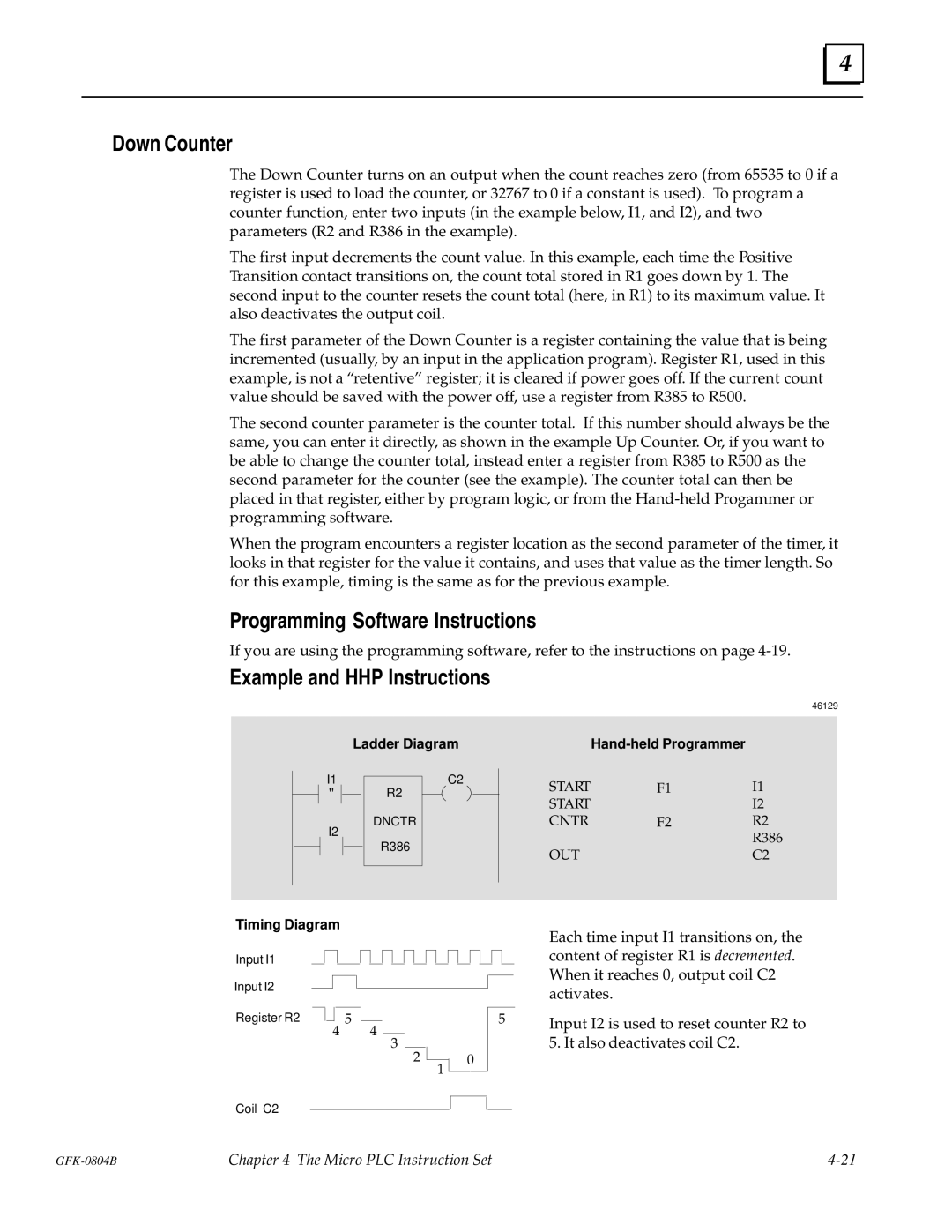
Ladder Diagram
C2
R2
DNCTR
R386
|
| |
START | F1 | I1 |
START |
| I2 |
CNTR | F2 | R2 |
|
| R386 |
OUT |
| C2 |
Timing Diagram
Input I1
Input I2
Register R2
5
4 4
3
2
1
0
Each time input I1 transitions on, the content of register R1 is decremented. When it reaches 0, output coil C2 activates.
5Input I2 is used to reset counter R2 to 5. It also deactivates coil C2.
Coil C2
Chapter 4 The Micro PLC Instruction Set |