F |
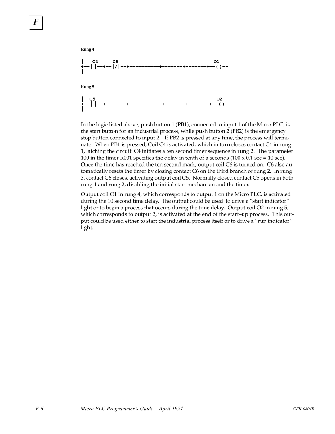
Rung 4
C4 | C5 | O1 |
+±± ±±+±±/±±+±±±±±±±±±±+±±±±±±±+±±±±±±±+±±( )±±
Rung 5 |
|
C5 | O2 |
+±± ±±+±±±±±±±+±±±±±±±±±±±+±±±±±±±+±±±±±±±+±±( )±±
In the logic listed above, push button 1 (PB1), connected to input 1 of the Micro PLC, is the start button for an industrial process, while push button 2 (PB2) is the emergency stop button connected to input 2. If PB2 is pressed at any time, the process will termi- nate. When PB1 is pressed, Coil C4 is activated, which in turn closes contact C4 in rung 1, latching the circuit. C4 initiates a ten second timer sequence in rung 2. The parameter 100 in the timer R001 specifies the delay in tenth of a seconds (100 x 0.1 sec = 10 sec). Once the time has reached the ten second mark, output coil C6 is turned on. C6 also au- tomatically resets the timer by closing contact C6 on the third branch of rung 2. In rung 3, contact C6 closes, activating output coil C5. Normally closed contact C5 opens in both rung 1 and rung 2, disabling the initial start mechanism and the timer.
Output coil O1 in rung 4, which corresponds to output 1 on the Micro PLC, is activated during the 10 second time delay. The output could be used to drive a ºstart indicatorº light or to begin a process that occurs during the time delay. Output coil O2 in rung 5, which corresponds to output 2, is activated at the end of the start±up process. This out- put could be used either to start the industrial process itself or to drive a ºrun indicatorº light.
Micro PLC Programmer's Guide ± April 1994 |