4 |
Contacts
The Micro PLC instruction set includes the following contacts:
± ± | |
| associated reference is = 1. |
± " ± | Positive transition contact. Passes power flow to the right for one |
| program cycle when its associated reference changes from 0 to 1. |
± / ± | |
| associated reference is = 0. |
± #± | Negative transition contact. Passes power flow to the right for one |
| program cycle when its associated reference changes from 1 to 0. |
Each of these contact types is described more fully on the pages that follow. If you are using the programming software, refer to the programming instructions below. If you are using the
General Programming Software Instructions for Contacts
1.Select the contact type using the function keys:
± ± | (F1) | |
± " ± | (Shift, F1) | Positive transition contact. |
± / ± | (F2) | |
± #± | (Shift, F2) | Negative transition contact. |
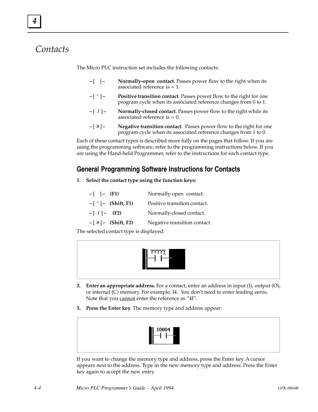
The selected contact type is displayed:
2.Enter an appropriate address. For a contact, enter an address in input (I), output (O), or internal (C) memory. For example: I4. You don't need to enter leading zeros. Note that you cannot enter the reference as ª4Iº.
3.Press the Enter key. The memory type and address appear:
If you want to change the memory type and address, press the Enter key. A cursor appears next to the address. Type in the new memory type and address. Press the Enter key again to accept the new entry.
Micro PLC Programmer's Guide ± April 1994 |