Manuals
/
Genicom
/
Computer Equipment
/
Printer
Genicom
LA36
manual
Standard 8-bit Code Table Left Half
Models:
LA36
1
133
195
195
Download
195 pages
19.85 Kb
130
131
132
133
134
135
136
137
Troubleshooting
Specs
Install
Centronics Compatible Signals
Default Sets
Cable Wiring
Maintenance
Problem Solution
Using the Diagnostic Functions
Changing Menu Access Options
Page 133
Image 133
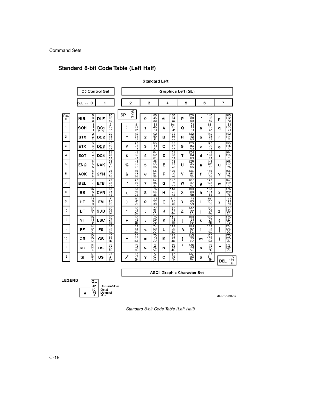
Command Sets
Standard
8-bit
Code Table (Left Half)
Standard
8-bit
Code Table (Left Half)
C-18
Page 132
Page 134
Page 133
Image 133
Page 132
Page 134
Contents
Genicom Matrix Printer LA36
FCC Compliance Statement
Page
Table of Contents
Printing
Maintenance
Supplies and Options
Resident Fonts Glossary GL-1 Index IN-1
Viii
About this Manual
Preface
Printer Models and Options
LA36N/LA36W
Organization
LA36N and LA36W Model Specifications
Maintenance
Xii
Introduction
Features
Options
Paper Handling
Parts of the Printer
Front View
Basic States of the Printer
Operations of the Control Panel
Control Panel Operations
Enter Top-of-Form Adjustment mode Not printing Off
Selecting Paper
Paper Specifications Paper Size
Printer Acoustical Feed-Backs
Paper Thickness and Number of Copies
Ready state but not receiving or printing data Pause state
Overview of Paper Operations
Levers and Buttons Used for Paper Handling
Adjusting for Paper Thickness
Paper Thickness Lever Positions
Using Single Sheets
Loading a Single Sheet of Paper
Setting Paper Select Lever and Left Paper Guide
Ejecting Single Sheets
Using Continuous Forms
Positioning the Paper Stack
Loading Continuous Forms Push Tractor and Rear Feed
12 mm
Adjusting Paper Tension
Always manipulate the metallic parts of the tractor unit
Loading Continuous Forms Pull Tractor and Bottom Feed
Removing the Tractor Unit
Installing the Tractor Unit for Pull-tractor Feed
Passing Continuous Forms Paper From Under the Printer
Setting Continuous Forms Paper on the Tractors
Recovering from an Unexpected Unloading Operation
Unloading Continuous Forms Push-Feed Mode
Tearing Off Continuous Forms Automatic-Tear-Off Advancing
Manual Tear-Off Advancing
Print Area Definition
Feeding and Positioning Paper
Abcdefghij ···
Line Feed/Form Feed
Top-of-Form Adjustment
Switching Paper Types
FF/LOAD button
Turn the printer off
Switching between Push-Feed and Pull-Feed
General Tips
Tips on Paper Handling
Multipart Forms
Envelopes
Printing
Selecting Print Features
Using the Control Panel
Using Commercial Software
Selecting Macro 1 or Macro
DEC
Macro 1 and Macro 2 Settings
Epson IBM
IBM&Epson mode
DEC mode
IBM mode
Epson mode
Adjustments Settings
Installation Settings
XON/XOFF
Selecting a Resident Font
Menu access All functions allowed
DEC PPL2 protocol
Changing the Protocol
Starting Printing
Starting or Stopping Printing
Stopping and Viewing Printing
Resuming Printing
Removing Single Sheets
Removing Printed Pages
Removing Continuous Forms
What is Set-Up Mode?
Using Set-Up Mode
How Set-Up Works
Entering the Set-Up Mode
OFF on
Initial Printout in the Set-Up Mode
Set-Up Mode Functions
Overview of the Set-Up Mode
Options with Pre-determined Values
Example Changing the Vertical Pitch
Enter the Set-Up mode
Select the Macro 2 function
Print the menu of the vertical pitch option
Example Changing the Left Margin
Options with Undetermined Values
Print the menu of the left margin option
Options with Both Pre-determined and Undetermined Values
Change the left margin from column 1 to column
Summary of the Set-Up Mode
Points to Remember
Printing the Printer Configuration
Printout of Factory SettingsUsing the Print Function
Required Options
Deciding Which Options to Change
Changing Macro 1 and Macro 2 Options
Macro 1 and Macro 2 Options List
Port Depnd
Macro 1 and Macro 2 Options and Values
IBM PPX24
LF=LFCR=CR
Tractor
Answerback
Wrap
US Ascii
Suppl
Ecma
IBM SET
Install Options List
Changing Install Options
English
Install Options and Values
Download buffer becomes. Even with 64K bytes
Larger the input buffer selected, the smaller
Input buffer, a minimal download buffer is
Provided. If you need a larger capacity for
None
Number of data bits Parity bit
Adjust Options and Values
AdjustingTop-of-Form Origin
Menu Access Option and Values
Changing Menu Access Options
Exiting and Saving
Using the Diagnostic Functions
Recalling Factory Settings
Printing Test
Start the printing test select the PRINT-Toption
Start the Hex Dump mode select the HEX-DUMPoption
Hex Dump Mode
Exit the Hex Dump mode
Examine the test
Sample Hex Dump
Setup Mode MACRO1 MACRO2
Set-Up Mode Quick Reference
Print Install Adjust Tests RCALL-FACT MENU-ACCES SAVE&EXIT
Cleaning
Maintenance
Cleaning and Vacuuming the Printer
Cleaning the Platen and Paper Bail Rollers
Replacing the Ribbon Cartridge
Cleaning the Print Head
Remove the new ribbon cartridge from its package and install
Replacing the Print Head
Solving problems
Trouble-Shooting
Print Quality Problems and Solutions
Problem Solution
Problem Solution
Paper Handling Problems and Solutions
Operating Problems and Solutions
Printer Failures
Diagnostic Functions
Checking Vertical Alignment
Adjust the vertical print alignment at Letter quality speed
Start the vertical alignment test
Exit the vertical alignment function
Vertical Alignment Adjustment
Supplies
Supplies and Options
LA30R-KA
LA30R-KC
Installing the Color Kit
Installing Options
Physical Specifications
Printer and Paper Specifications
Functional Specifications
Fonts
Character sets
Barcode
Performance Specifications
Print Area
Paper Specifications
Print Area for Continuous Forms
Paper Thickness
Do not use in high humidity environments
Command Sets
DEC PPL2 Quick Reference Guide
Escape 1/11, introduces an escape sequence
Conventions
Control string
C0 Control Code
Positioning Controls
C1 Control Code
CSI Pn ... Pn u
Sheet Size and Margins
Type Size and Spacing, Managing Implicit Cursor Motion
Font Management and Attribute Selection
CSI Pn . . . Pn u
Tabs
CSI Pn . . . Pn
TBC
Selecting Character Sets
Ascii
SCS Final Characters
Reports
Encodedmessage
DCS Ps Pn2 Pn3
String ST
CSI Ps n
Miscellaneous
Decbar
Barcode Printing
Decsbca
CSI Ps1 Pn2
Decsbca CSI 0’q
Sixel Graphics Device Control String Envelope
Sixel Graphics Grid Size defined by Pn3
Sixel Graphics Protocol Selector Ps1
Pn1 Pn2 Pn3 Pn4
Sixel Graphics Control Codes
Pc Pu Px Py Pz
Standard 8-bit Code Table Left Half
Standard 8-bit Code Table Right Half
Ascii
Designating and Invoking Character Sets
ISO JIS Ascii
National Replacement Character Sets
IBM Proprinter X24E and XL24E Quick Reference Guide
Print Mode Control
ESC
Horizontal Control
Vertical Control
Tabulation
Color Selection
Formatting
Character Set Control
Bit Image Graphics
Downloading
ESC EM
Cut Sheet Feeder Control
ESC EM E
ESC EM R
Epson ESC/P2 Quick Reference Guide
ESC P
ESC M
Set line spacing to n/360 inch 0 ≤ 255 ESC + n
D2 ≤
Character codes
ESC =
DEL
ESC #
Font Selection and Downloading
ESC @
Command Sets
Parallel Interface
Interface Information
Centronics Compatible Signals
To printer HostClk High in reverse data transfer phase
Ieee 1284-B Nibble Mode signals
Serial Interface
Serial Options
Cable Wiring
Buffer Control
DTR
XON/XOFF DC1/DC3
DEC PPL2 Protocol
Character Sets
Character Sets
Character Sets
Character Sets
Character Sets
Character Sets
Character Sets
Character Sets
Character Sets
Character Sets
Character Sets
Character Sets
Character Sets
Character Sets
Character Sets
Character Sets
Character Sets
Character Sets
Code
Default Sets
Code
Ecma
Turkish
ISO Latin Hungarian Slovenian Polish
Elot Latin Polish
Mazowian Kamenicky Cyrillic
Lithuanian
IBM Set 1/2
IBM Proprinter X24E and XL24E Protocol
IBM Set
National Character Sets
Epson ESC/P2 Protocol
Common Characters
National Characters
Character Sets
Resident Fonts
Timeless outline Nimbus Sans outline
Glossary
Carriage Return CR
Command Set
Centronics Interface
Column
Dot Matrix
Defaults
Downloading
Dpi
Line Feed LF
Normal Mode
Line Spacing
Lpi
Pitch
Set-Up Mode
Platen
Proportional Spacing
Soft Fonts
Single Sheets
Software
Tear Bar
Answer ENQ
Index
Auto Ansbk
BIT&PARITY Bottom MRG
Horz Pitch
Form Lengh
Language Left Margn
IN-3
Vert Pitch
Top
Page
Image
Contents