Interface Information
Pin | Direction | Signal | Description |
31 | To printer | Init L | Set to high for Reverse Channel operation |
|
|
|
|
32 | From printer | DataAvail L | Reverse channel: Data 0 and 4 |
|
|
|
|
33 |
|
| Not used |
|
|
|
|
34 |
|
| Not used |
|
|
|
|
35 |
|
| Not used |
|
|
|
|
36 | To printer | SelectIn L | Set to high for Reverse Channel |
|
|
|
|
Serial Interface
Use the cable that comes with the printer or the Digital BC16E cable or equivalent. If you prepare a cable separately, the cable connector at the printer side should be a male Modified Modular Jack (MMJ) or the equivalent that conforms to EIA standards.
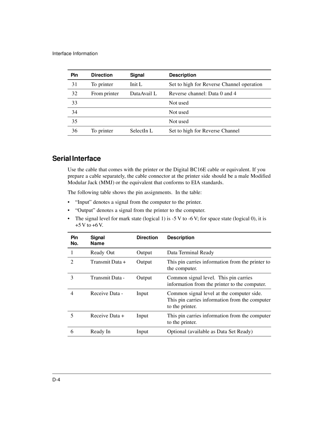
The following table shows the pin assignments. In the table:
•“Input” denotes a signal from the computer to the printer.
•“Output” denotes a signal from the printer to the computer.
•The signal level for mark state (logical 1) is
Pin | Signal | Direction | Description |
No. | Name |
|
|
|
|
|
|
1 | Ready Out | Output | Data Terminal Ready |
|
|
|
|
2 | Transmit Data + | Output | This pin carries information from the printer to |
|
|
| the computer. |
|
|
|
|
3 | Transmit Data - | Output | Common signal level. This pin carries |
|
|
| information from the printer to the computer. |
|
|
|
|
4 | Receive Data - | Input | Common signal level at the computer side. |
|
|
| This pin carries information from the computer |
|
|
| to the printer. |
|
|
|
|
5 | Receive Data + | Input | This pin carries information from the computer |
|
|
| to the printer. |
|
|
|
|
6 | Ready In | Input | Optional (available as Data Set Ready) |
|
|
|
|
