Contents
Frequency and Period Measurement Errors
Zeroauto ZEROAUTO?
IMMediate
Chapter Multimeter Command Reference
Appendix a
Appendix B
Contents
HEWLETT-PACKARD Warranty Statement
Documentation History
Manufacturer’s Name
July 31 Jim White, QA Manager
Business Reply Mail
Page
Using This Chapter
HP E1312A and HP E1412A Multimeter Module Setup
Setting the Module Address Switch
Setting the Line Frequency Reference
Interrupt Priority
Checking the Line Frequency Reference
Page
Multimeter Functional Connections
Switch Module Analog Bus Connections
Voltage Measurement Connections
Wire Ohms Measurement Connections
Initial Operation
HP E1312A and HP E1412A Multimeter Module Setup Chapter
Function Prototype
HP E1312A and HP E1412A Multimeter Module Setup Chapter
Thermal EMF Errors
Measurement Tutorial
DC Voltage Measurements
Thermoelectric Voltages
Loading Errors dc volts Leakage Current Errors
Common Mode Rejection CMR
Rejecting Power Line Noise Voltages
Noise Caused by Ground Loops
Noise Caused by Magnetic Loops
Resistance Measurements
Wire Ohms Measurements
Set to 2-wire ohms function
Power Dissipation Effects
Errors in High Resistance Measurements
Making High-Speed DC and Resistance Measurements
True RMS AC Measurements
DC Current Measurement Errors
Common Crest Factors Example
Crest Factor Errors non-sinusoidal inputs
Function and Range Change Internal Offset Correction
Loading Errors ac volts
Temperature Coefficient Errors
AC Measurements Below Full Scale
Voltage Measured = Vin2+ Noise2
Low-Level Measurement Errors
AC Current Measurement Errors
Frequency and Period Measurement Errors
Making High-Speed AC Voltage or Current Measurements
AC Signal Filter DC Input Resistance
Measurement Configuration
Number of Power Line Cycles Nplc Resolution
Chapter HP E1312A/E1412A Multimeter Application Information
SENSeZEROAUTO Offonceon
Null Relative Function
Math Operations CALCulate Subsystem
CONFfunction
DB Measurements
DBm Measurements
Storing the dB Reference Value
Storing the dBm Reference Resistance Value
HP E1312A/E1412A Multimeter Application Information Chapter
Triggering the Multimeter
TRIGgerSOURce EXTernal
Checking the Trigger Source
Wait-for-Trigger State
Bus Triggering
Checking the Trigger Count Inserting a Trigger Delay
Example Setting the Trigger Count
Example Inserting a Trigger Delay
Default Trigger Delays
Querying Delay Time Sample Count
Example Setting the Sample Count
Checking the Sample Count
HP VTL Software Visa
HP E1312A and HP E1412A Multimeter Application Examples
Making Multimeter Measurements
MEASure Command
MEASURE2 Source Code File
MEASURE1 Source Code File
Init
MEASURE3 Source Code File
MEASURE4 Source Code File
HP E1412A Multimeter and Switch Module Synchronization
Synchronizing Multimeter With a Switch Module
See -5 for the HP E1312A/E1412A Multimeter status system
Retrieve the readings from the multimeter
Set up the Multimeter
Now set up the switch module
Check the multimeter for system errors
Multimeter Status System Examples
RST CLS *ESE Init OPC
Synchopc Source Code File
RST Init FETC?
Synchmav Source Code File
End Loop Check the multimeter for system errors
Limittst Source Code File
Loop
Programming Example
Device Configuration
Page
HP E1312A/E1412A Multimeter Application Information Chapter
Command Types
Common Command Format
Command Format
Command
Abbreviated Commands Implied Commands
Separator
Parameters
Linking Commands
PLC
Multimeter Range and Resolution Tables
Scpi Command Reference
AC Voltage Range versus Resolution
AC Current Range versus Resolution
Related Commands INITiate, TRIGger
ABORt
Aborting a Measurement
CALCulate
Subsystem Syntax
Valid Math/Measurement Function Combinations
AVERageMINimum?
AVERageAVERage?
AVERageCOUNt?
AVERageMAXimum?
DBMREFerence?
DBREFerence
DBREFerence?
DBMREFerence
Example Query the Calculate Math Function
FUNCtion
FUNCtion?
Parameter Summary Example
LIMitUPPer?
LIMitLOWer
LIMitLOWer?
LIMitUPPer
STATe?
NULLOFFSet
NULLOFFSet?
STATe
Comments
CALibration
COUNt?
LFRequency
Example Enter a New Calibration Security Code
Example Query the Line Frequency Setting
LFRequency?
SECureCODE
Example Set the Calibration State to Unsecured
SECureSTATe
SECureSTATe?
STRing
Example Query the Calibration Message
STRing?
VALue
VALue?
Zeroauto
CAL?
CALibration?
Command Setting
CONFigure
Function Range Resolution
Default Settings for CONFigure Command by Function
Example Making AC Current Measurements
CURRentAC
Example Making DC Current Measurements
CURRentDC
ResolutionMINMAXDEF selects the frequency function
FRESistance
Example Making 4-Wire Ohms Measurements
PERiod
Example Making 2-Wire Ohms Measurements
Resolution Minmaxdef
Example Making AC Voltage Measurements
VOLTageAC
Example Making DC Voltage Measurements
VOLTageDC
Sense HI and LO input
VOLTageDCRATio
String Returned
CONFigure?
POINts?
Data
Example Transferring Stored Readings to Output Buffer
FETCh?
INITiate
IMMediate
Example Placing Multimeter in Wait-For-Trigger State
IMPedanceAUTO?
Example Query the Input Impedance Mode
INPut
IMPedanceAUTO
MEASure
MEASCURRAC? 1,MAX
CURRentAC?
MEASCURRDC? .1,MAX
CURRentDC?
FREQuency?
MEASFRES? 1500,MAX
FRESistance?
PERiod?
RESistance?
VOLTageAC?
VOLTageDC?
Example Making DC Voltage Ratio Measurements
VOLTageDCRATio?
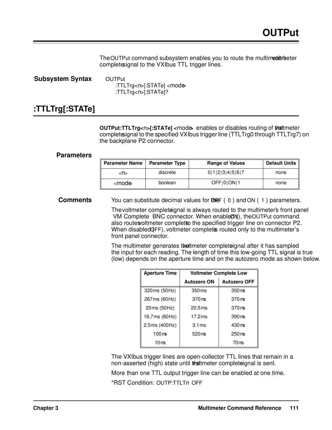
OUTPut
TTLTrgSTATe
RST Condition OUTPTTLTn OFF
TTLTrgSTATe?
Example Route Voltmeter Complete to Trigger Line
Example Query Voltmeter Complete Destination
Example Transfer Readings Directly to Output Buffer
READ?
SAMPle
COUNt
RST Condition Sampcoun Example Set the Sample Count
SAMPCOUN?
Example Query the Sample Count
SENSe
Zero Auto Offonceon AUTO?
Function
Example Query the Measurement Function
CURRentACRANGe
CURRentACRANGe?
Example Query the AC Current Measurement Range
CURRentACRANGeAUTO?
Example Disable AC Current Autoranging
Example Query the AC Current Autorange Mode
CURRentACRANGeAUTO
CURRentACRESolution?
CURRentACRESolution
Example Query the Aperture Time
CURRentDCAPERture
CURRentDCAPERture?
Example Set an Aperture Time of 16.7ms
CURRentDCNPLC
CURRentDCNPLC?
Example Query the DC Current Integration Time
Example Query the DC Current Measurement Range
CURRentDCRANGe
CURRentDCRANGe?
Example Set the DC Current Range to 3A
CURRentDCRANGeAUTO?
Example Disable DC Current Autoranging
Example Query the DC Current Autorange Mode
CURRentDCRANGeAUTO
CURRentDCRESolution?
CURRentDCRESolution
DETectorBANDwidth
Example Query the Detector Bandwidth
DETectorBANDwidth?
FREQuencyAPERture
FREQuencyAPERture?
Example Query the Measurement Range
FREQuencyVOLTageRANGe
FREQuencyVOLTageRANGe?
Example Set the Voltage Range for Frequency Measurements to
FREQuencyVOLTageRANGeAUTO?
Example Disable Autoranging
Example Query the Autorange Mode
FREQuencyVOLTageRANGeAUTO
FRESistanceAPERture?
FRESistanceAPERture
FRESistanceNPLC
FRESistanceNPLC?
Example Query the Integration Time
FRESistanceRANGe?
FRESistanceRANGe
FRESistanceRANGeAUTO?
FRESistanceRANGeAUTO
RST Condition Fresres 1mΩ 1E-03
FRESistanceRESolution
FRESistanceRESolution?
Example Query the Resolution
PERiodAPERture
PERiodAPERture?
RST Condition 0.1 100ms Example Set the Aperture Time
Example Query the Period Voltage Range
PERiodVOLTageRANGe
PERiodVOLTageRANGe?
Example Set the Voltage Range for Period Measurements to
PERiodVOLTageRANGeAUTO?
PERiodVOLTageRANGeAUTO
RESistanceAPERture?
RESistanceAPERture
RESistanceNPLC?
RESistanceNPLC
RESistanceRANGe
RESistanceRANGe?
RST Condition Resrang 1kΩ Example Change the Range
RESistanceRANGeAUTO?
RESistanceRANGeAUTO
RESistanceRESolution
RESistanceRESolution?
Example Change the Resolution
VOLTageACRANGe?
VOLTageACRANGe
Example Disable AC Voltage Autoranging
VOLTageACRANGeAUTO
VOLTageACRANGeAUTO?
VOLTageACRESolution
VOLTageACRESolution?
RST Condition 1E-04 Example Change the Resolution
VOLTageDCAPERture?
VOLTageDCAPERture
VOLTageDCNPLC?
VOLTageDCNPLC
VOLTageDCRANGe?
VOLTageDCRANGe
VOLTageDCRANGeAUTO?
VOLTageDCRANGeAUTO
VOLTageDCRESolution?
VOLTageDCRESolution
Example Query the Autozero Mode
Example Disable Autozero
QUEStionableCONDition?
PRESet
QUEStionableENABle
STATus
QUEStionableEVENt?
QUEStionableENABle?
VERSion?
ERRor?
Example Reading the Error Queue
SYSTem
RST Condition Trigcoun Example Set the Trigger Count
TRIGger
DELay
Example Set the Trigger Delay
Example Query the Trigger Count
Example Disable Automatic Trigger Delay
DELay?
DELayAUTO
Example Query the Trigger Delay
Example Query the Trigger Delay Mode
DELayAUTO?
Related Commands INITiate, READ?, MEAS?
SOURce
Example Set the Sample Source
Example Query the Trigger Source
SOURce?
Category Command Title Description
Ieee 488.2 Common Command Quick Reference
ESE and *ESE?
Example Enable All Error Events
ESR?
RST does not affect
SRE and *SRE?
STB?
HP E1412A C-size 6½-Digit Multimeters
Scpi Command Quick Reference
Data
67sMINMAX
Zeroauto Offonceon
DC Characteristics
HP E1312A and HP E1412A Multimeter Specifications
60 Hz 50 Hz
Measuring Characteristics
Operating Characteristics
True RMS AC
AC Characteristics
True RMS AC Voltage
System Speeds 10
Accuracy Specifications ±% of reading 1
Frequency and Period Characteristics
Configuration Rates 14/sec Autorange Time
General Specifications
Understanding the % of reading Error
To Calculate Total Measurement Error
Total Measurement Error
Number of Digits and Overrange
Interpreting Multimeter Specifications
Accuracy
DC Voltage, DC Current, and Resistance Measurements
Configuring for High Accuracy Measurements
Execution Errors
123Numeric overflow
112Program mnemonic too long
113Undefined header
121Invalid character in number
211Trigger ignored
To -168Block data errors
To -178Expression errors
221Settings conflict
350Too many errors
330Self-test failed
440Query Unterminated after indefinite response
Cannot use overload as math reference
Cannot achieve requested resolution
Invalid secure code
Cal signal measurement out of range
Cal signal frequency out of range
Cal secured
No cal for this function or range
HP E1312A and HP E1412A Multimeter Error Messages Appendix B
Measurement Speed and Accuracy Trade-offs
Measurement Speed and Accuracy Trade-offs Appendix C
HP E1312A/E1412 Special Function
Minimize Number Command Response Sessions
General Guidelines for Increasing Measurement Speed
Avoid Function Changes Avoid Aperture Changes
Decrease Aperture Time or NPLCs
Set Autozero to Once or OFF Turn Autorange
INITFETCH?
Setting the Resolution
Index
197
Index
124
Index
Index
Error, 180
See online help
Cycles, 27, 38, 123, 132, 140
Errors
130
Setting resolution, 15, 38
160
Index