INSTALLATION
Laying and connecting the guide wire
1.Before laying and connecting the guide wire, it is important to give consideration to the length of the guide loop, especially in large or complex installations. If the guide loop is longer than 400 metres the robotic lawnmower can have difficulty following the guide wire.
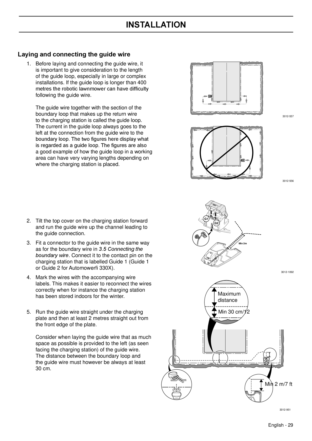
The guide wire together with the section of the boundary loop that makes up the return wire to the charging station is called the guide loop. The current in the guide loop always goes to the left at the connection from the guide wire to the boundary loop. The two figures here display what is regarded as a guide loop. The figures are also a good example of how the guide loop in a working area can have very varying lengths depending on where the charging station is placed.
2.Tilt the top cover on the charging station forward and run the guide wire up the channel leading to the guide connection.
3.Fit a connector to the guide wire in the same way as for the boundary wire in 3.5 Connecting the boundary wire. Connect it to the contact pin on the charging station that is labelled Guide 1 (Guide 1 or Guide 2 for Automower® 330X).
4.Mark the wires with the accompanying wire labels. This makes it easier to reconnect the wires correctly when for instance the charging station has been stored indoors for the winter.
5.Run the guide wire straight under the charging plate and then at least 2 metres straight out from the front edge of the plate.
Consider when laying the guide wire that as much space as possible is provided to the left (as seen facing the charging station) of the guide wire.
The distance between the boundary loop and the guide wire must however be always at least 30 cm.
G1![]()
![]()
![]()
![]()
![]()
![]()
G2
Min 2m
Maximum distance
![]() Min 30 cm/12”
Min 30 cm/12”
![]() Min 2 m/7 ft
Min 2 m/7 ft
English - 29