PRESENTATION
2.1 What is what?
| 2 | 3 |
|
|
|
|
| 9 |
|
|
|
|
|
|
| ||
|
|
|
|
|
|
|
| |
1 |
|
|
|
|
|
| 8 |
|
|
|
|
|
|
|
|
| |
|
|
| 6 |
|
|
|
|
|
|
|
|
|
|
|
|
| 10 |
4 | 5 |
|
|
|
| 7 |
|
|
|
|
|
|
|
|
|
| |
11 |
|
|
|
|
|
| 18 |
|
|
|
| 14 |
|
|
|
| |
12 |
|
|
|
|
|
|
| |
|
|
|
|
|
|
| 19 | |
|
| 13 |
|
|
|
|
| |
|
|
|
|
|
|
|
| |
|
|
|
|
|
|
| 21 | 22 |
|
| 20 |
|
|
|
|
| |
|
| 15 |
|
|
|
|
| |
|
|
|
|
| 17 |
|
| |
|
|
|
|
| 16 |
|
| |
|
|
|
|
|
|
| 31 | |
|
|
|
|
|
|
|
| |
23 |
|
|
| 27 |
| 28 |
| 30 |
|
| 25 | 26 |
|
| 29 | ||
|
|
|
|
| ||||
|
|
|
|
|
| |||
| 24 |
|
|
|
|
|
| 32 |
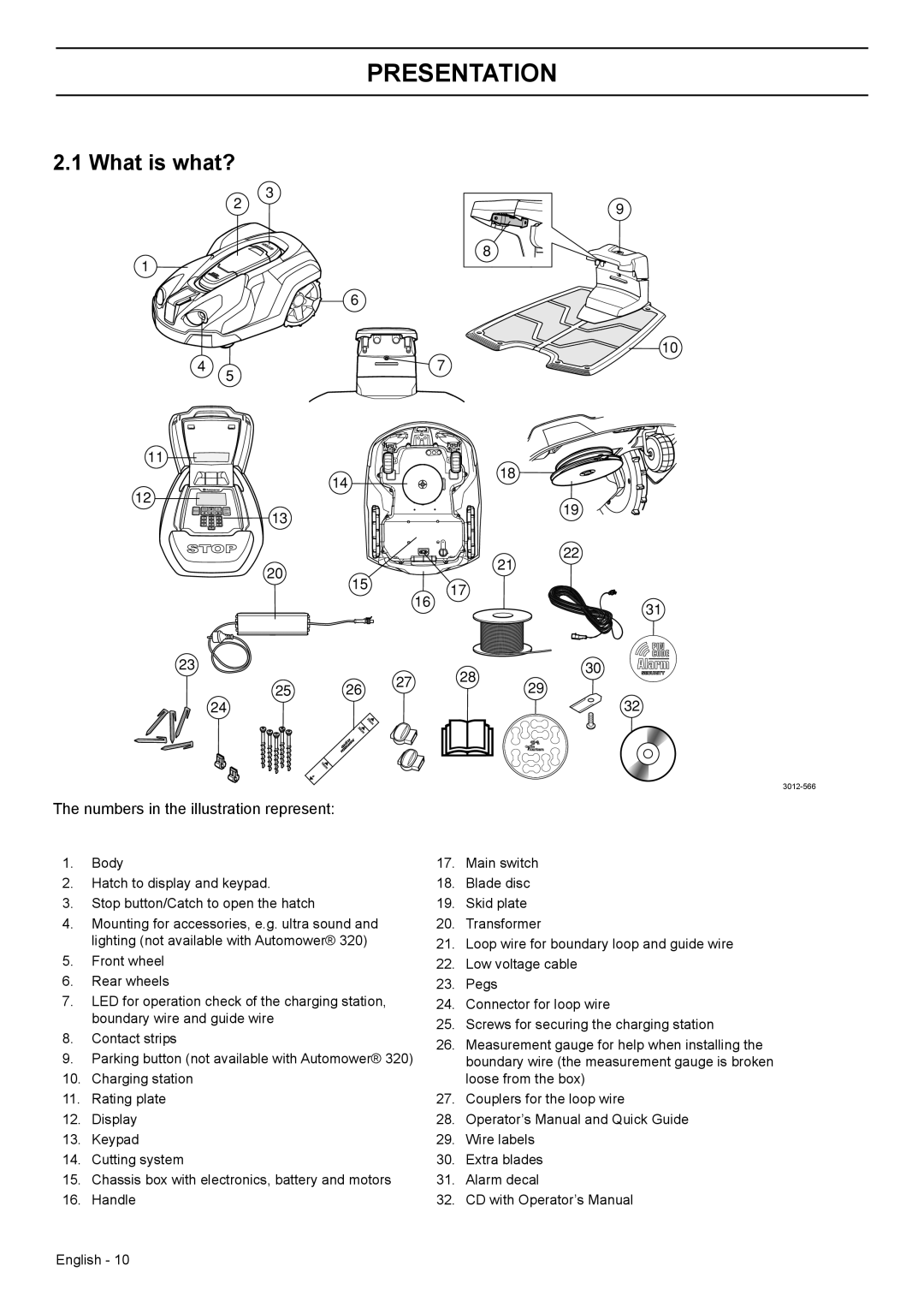
The numbers in the illustration represent:
1.Body
2.Hatch to display and keypad.
3.Stop button/Catch to open the hatch
4.Mounting for accessories, e.g. ultra sound and lighting (not available with Automower® 320)
5.Front wheel
6.Rear wheels
7.LED for operation check of the charging station, boundary wire and guide wire
8.Contact strips
9.Parking button (not available with Automower® 320)
10.Charging station
11.Rating plate
12.Display
13.Keypad
14.Cutting system
15.Chassis box with electronics, battery and motors
16.Handle
17.Main switch
18.Blade disc
19.Skid plate
20.Transformer
21.Loop wire for boundary loop and guide wire
22.Low voltage cable
23.Pegs
24.Connector for loop wire
25.Screws for securing the charging station
26.Measurement gauge for help when installing the boundary wire (the measurement gauge is broken loose from the box)
27.Couplers for the loop wire
28.Operator’s Manual and Quick Guide
29.Wire labels
30.Extra blades
31.Alarm decal
32.CD with Operator’s Manual
English - 10