Installation
This section describes how to install the ATM Module using the example of an IBM 8271 Nways Ethernet LAN Switch Model 624 device. Installation is similar for all devices compatible with this ATM Module.
1If the Switch is connected to the network, turn off the power to the switch and disconnect the switch from the main power supply and the network.
2Place the Switch on a flat, clean, hard, working surface.
3Locate and remove the blanking plate which covers the ATM Module slot. Retain the blanking plate and the screws for future use.
Refer to the manual which accompanies your Switch to locate the slot where the ATM Module is located.
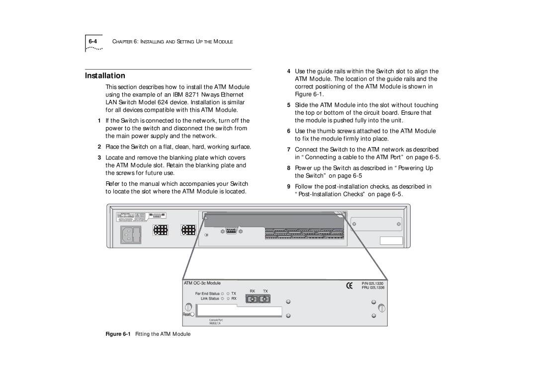
4Use the guide rails within the Switch slot to align the ATM Module. The location of the guide rails and the correct positioning of the ATM Module is shown in Figure
5Slide the ATM Module into the slot without touching the top or bottom of the circuit board. Ensure that the module is pushed fully into the unit.
6Use the thumb screws attached to the ATM Module to fix the module firmly into place.
7Connect the Switch to the ATM network as described in “Connecting a cable to the ATM Port” on page
8Power up the Switch as described in “Powering Up the Switch” on page
9Follow the