Manuals
/
IBM
/
Computer Equipment
/
Switch
IBM
ATM OC-3c
manual
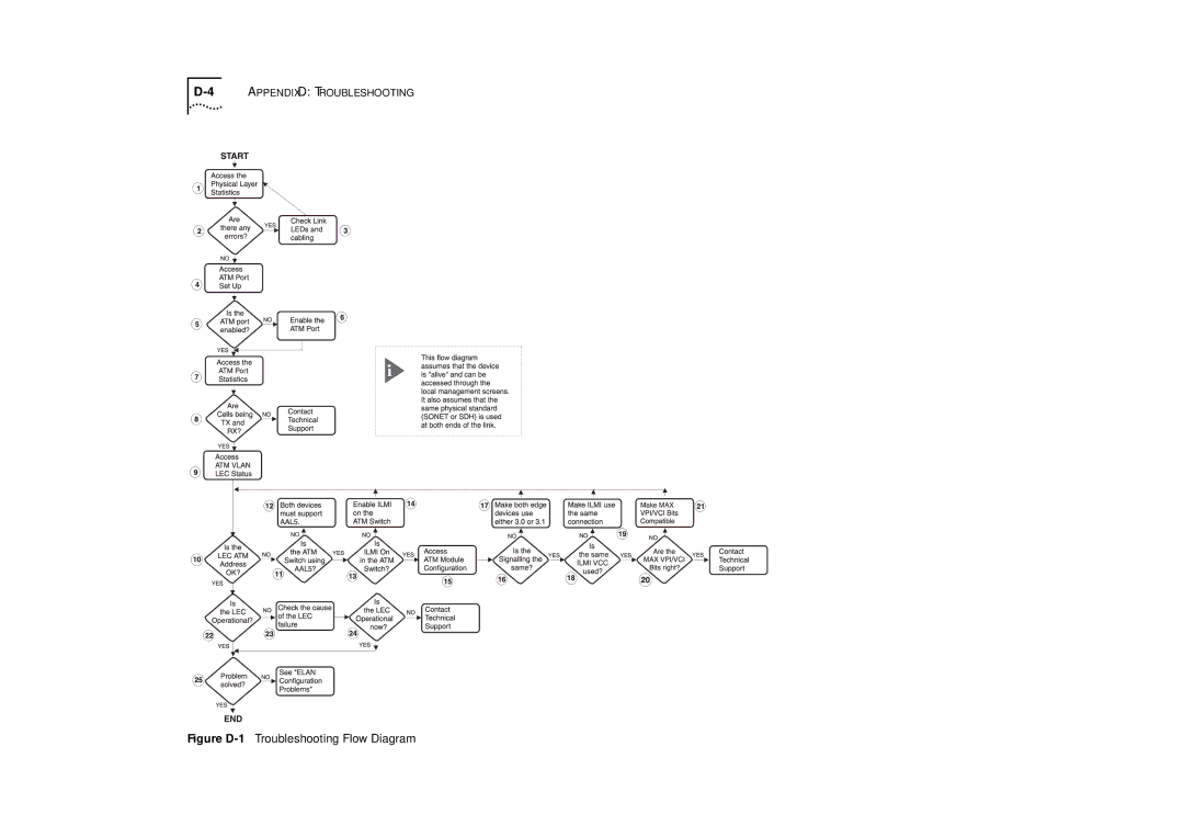
Figure D-1Troubleshooting Flow Diagram
Models:
ATM OC-3c
1
98
140
140
Download
140 pages
60.63 Kb
95
96
97
98
99
100
101
102
Troubleshooting
Specifications
Install
Error codes
Is Signalling Compatible?
Undefined Error
Connecting to BUS
Warranty
ATM Configuration Rules
Problem Solution
Page 98
Image 98
D-4
A
PPENDIX
D: T
ROUBLESHOOTING
Figure
D-1
Troubleshooting Flow Diagram
Page 97
Page 99
Page 98
Image 98
Page 97
Page 99
Contents
User’s Guide
First Edition October
Research Triangle Park NC
Contents
Accessing Management Features Screen Map
Glossary Bibliography
Page
Terminology
About this Guide
Introduction
ATM Terminology
Task Location
Finding Information in This Guide
Conventions
Icon Alerts you to
Related Documentation
Bold
About this Guide
Features and Benefits
ATM Benefits
ATM Module Features
Wire Rate Transmission on ATM port
Network Layer Concepts
Layered Network Architecture
What is LAN Emulation LANE?
Upper Layer Protocols
LAN Emulation Client LEC
LAN Emulation Configuration Server Lecs
LAN Emulation Components
LAN Emulation Server LES
LAN Emulation Components in Your Network
LAN Emulation and IBM Devices
Locating the Lecs
Joining the Elan
LEC must know the name of the Elan it is to join
If the destination MAC address is listed in the ARP Table
Address Resolution
Mapping Ethernet and ATM Addresses
What Happens to Broadcast and Multicast Frames?
LAN Emulation Address Resolution Protocol Learp
What Happens to Unicast Frames?
ATM is Cell-based
Asynchronous Transfer Mode ATM Layer
ATM Adaptation Layer AAL
ATM is Service Transparent
ATM is Connection-oriented
Virtual Path Identifier VPI Virtual Channel Identifier VCI
7Switching Cells using VPI and VCI values
Permanent Virtual Circuits PVCs
Switched Virtual Circuits SVCs
ATM Interfaces
Networkhostidentifier
Interim Local Management Interface Ilmi
ATM Address Registration
ATM Layer and Cell Structure
10ATM Cell Structure
Physical Layer
Sonet STS-3c
16CHAPTER 2 Network Layer Concepts
Virtual LAN Concepts
What is a Virtual LAN VLAN?
Creating Inter-switch VLANs
Extending VLANs into the ATM Network
2VLAN to Elan Mapping
Extending VLANs into the ATM Network
4CHAPTER 3 Virtual LAN Concepts
Does your existing ATM network have sufficient resources?
Putting Your ATM Network Together
Planning Your Network
Can your ATM devices communicate with each other?
ATM Configuration Rules
Extending VLANs Through the ATM Network
Are the LAN Emulation services configured correctly?
ATM Connections Within Your Network
1SVC Signalling Not Supported in Remote Edge-device
Network Configuration Examples
ATM Backbone in the Building
Campus Configuration
Campus Configuration
3Resilient Link Configuration
Making a Building Resilient to Network Failure
Installing and Setting UP the Module
Following Safety Information
Îïàñíî
Ebezpečí
Device Support
Pre-installation Procedure
Check the Power Supply
Installation
1Fitting the ATM Module
Powering Up the Switch
Post-Installation Checks
Connecting a cable to the ATM Port
Power On Self Test Post
LED Summary
Checking the Physical Connections
Checking the Power Supply
Checking that the ATM Module is Installed Correctly
8CHAPTER 6 Installing and Setting UP the Module
Keyboard Shortcuts
Accessing Management Features
Screen Map
Correcting Text Entry
Screen Map
Logging On
Main Banner
Automatic Logout
User Name Default Access Level Password
Logging Off
Managing the ATM Module
1Management Screen Map
Configuring an ATM Port
2ATM Module Configuration Screen
Configuring an ATM Port
Desired Value of VPI Number of bits Required
3ATM LEC Setup Screen
4Switch Management Screen
Displaying all VLANs
ATM Port Setup
5VLAN Selected Screen
7ATM Port Setup Screen
Problem Solution
Mapping Far End MAC Addresses
8ATM ARP Table Screen
Creating a MAC Address to ATM Entry
Mapping Far End MAC Addresses
Updating Address Entries
Displaying an ATM Connection
Finding an Address Entry
Deleting an Address Entry
Setting Up Resilient Links
Finding an ATM Connection
10Software Upgrade Screen
Upgrading Software
Error Messages
Download successful
Status Messages
Active
Load Paused
Monitoring the ATM Module
1Status Monitoring Screen Map
Physical Connection
Statistics Overview
MonitoringUse
ATM Physical Layer Statistics screen
2Switch Management Screen
ATM Port Statistics
4CHAPTER 9 Monitoring the ATM Module
ATM Vlan LEC Status
4ATM Vlan LEC Status Screen
Undefined Error
State Possible Causes Possible Solutions None
Timeout
LEC State Description
Parameters
State Possible Causes Possible Solutions Invalid Request
State Possible Causes Possible Solutions Duplicated ATM
Duplicate LAN
Access Denied
State Possible Causes Possible Solutions Insufficient
State Possible Causes Possible Solutions Invalid
No Configuration
Configuration
State Possible Causes Possible Solutions
Error
Connecting to BUS
ATM Physical Layer Statistics
Following button is available on this screen
ATM Physical Layer Statistics
Using Physical Layer Statistics to Troubleshoot
ATM Physical Layer Statistics
14CHAPTER 9 Monitoring the ATM Module
World Trade Safety Information
Safety Information
Safety Notices
2APPENDIX a Safety Information
Safety Notices
Neodstraňujte desky modulů, pokud je připojeno napájení
Safety Notices
6APPENDIX a Safety Information
Safety Notices
8APPENDIX a Safety Information
Screen Access Rights
2APPENDIX B Screen Access Rights
ATM Cable Specification
ATM Module Technical Specifications
Environmental Specifications
Numerical Aperture
Specification Description
Does the Cable Provide Sufficient Bandwidth?
Example
4APPENDIX C ATM Module Technical Specifications
Troubleshooting
How to Use this Guide to Troubleshoot
Using LEDs
Identifying the Problem
Figure D-1Troubleshooting Flow Diagram
Access the Physical Layer Statistics Screen
Are there Physical Layer Errors?
Access the ATM Port Setup Screen
Check the Physical Connections
Access the ATM Port Statistics Screen
Is the ATM Port Enabled?
Enable the ATM Port
Are Cells being transmitted and received?
Is the ATM Switch Using AAL5?
Access the ATM Vlan LEC Status Screen
Is the LEC ATM Address Valid for the Default VLAN?
Make Signalling Compatible
Access the ATM Module Configuration Screen
Is Signalling Compatible?
Both Devices Must be AAL5 Compliant
Are the MAX VPI and VCI Bits Compatible?
Is the Ilmi Connection Set Up Correctly?
Make Ilmi VPI/VCI Same at Both Ends of the Link
Make the MAX VPI and VCI Bits Compatible
Why has the LEC Operation Failed?
Operational
State Possible Causes
LEC is trying to join
Is the LEC Operational Now?
Are the LECs on the Same Emulated LAN?
Elan Configuration Problems
Has the Problem been Solved?
Re-map or Route the LEC
Is There Still a Problem?
Is the MAC Address in the Switch Database?
Enter the MAC Address in the Switch Database
Use routing
Solving Known Problems
Shuts itself down after a
Power Supply Problems
Switch powers up but then
Few minutes
Self Test Post
Power On Self Test Post Failure
ATM Module Fails Power on
Cable Connection Problems
Far End Status LED indicates
Connections
ATM Problems
Only showing reserved ATM
Other
Vlan or Elan Problems
Communicate with each
Insufficient Resources
Example
To clean the cable connectors
Cleaning Dirty Fiber Optic Connectors
To clean fiber optic connectors on the ATM Module
Voice Support
Technical Support and Service
Electronic Support
IBM Bulletin Board System
2APPENDIX E Technical Support and Service
Trademarks
Production Status
Statement of Limited Warranty
IBM Warranty for Machines
Warranty Service
Extent of Warranty
Limitation of Liability
Electronic Emission Notices
Federal Communications Commission FCC Statement
European Union EU Statement
Information To The User
How to Identify and Resolve Radio-TV Interference Problems
ATM Forum
ATM Switch
Glossary
Cell Header
Byte
Cell
Connectionless
LAN Emulation Lane
Link
OC-n
Multiplex
Octet
Payload
Telnet
UNI
VCI
Virtual Channel
LAN Emulation Lane
Asynchronous Transfer Mode ATM
Bibliography
Books
Bibliography
Index
ATM
SDH STM-1
Sonet
Index
Top
Page
Image
Contents