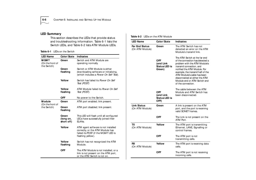
LED Summary
This section describes the LEDs that provide status and troubleshooting information. Table
Table
LED Name | Color/State | Indicates |
MGMT | Green | Switch and ATM Module are |
(On the front of |
| operating normally. |
the Switch) | Green | Switch or ATM Module is either |
| ||
| flashing | downloading software or initializing, |
|
| (which includes a Power On Self Test). |
| Yellow | Switch has failed its Power On Self |
|
| Test (POST) |
| Yellow | ATM Module failed its Power On Self |
| flashing | Test (POST). |
| OFF | No power to the Switch. |
Module | Green | ATM port enabled; link present. |
(On the front of | Green | ATM port disabled; link present. |
the Switch) | ||
| flashing |
|
| Green | This LED will flash until all configured |
| (long on, | LECs have successfully joined their |
| short off) | ELANs. |
| Yellow | ATM agent software is not installed |
|
| correctly, or the ATM Module has |
|
| failed its POST (if the MGMT LED is |
|
| flashing yellow). |
| Yellow | Switch has not recognized the ATM |
| flashing | Module. |
| OFF | The ATM Module is not installed, or a |
|
| link is not present on the ATM port, |
|
| or the ATM Switch is not on. |
Table
LED Name | Color/State | Indicates |
|
|
|
Far End Status | Green | The ATM Switch has not |
(On ATM Module) |
| detected an error on the ATM |
|
| Module’s transmit link. |
| OFF | The ATM Switch at the far end |
| of the connection has detected a | |
| (and Link | problem with the ATM Module’s |
| Status LED is | transmit connection, and |
| Green) | notified the ATM Module. For |
|
| example, the transmit half of the |
|
| ATM Module’s cable has been |
|
| disconnected at either the ATM |
|
| Module end or ATM Switch end |
|
| of the connection. |
| OFF | The cable between the ATM |
| Module and ATM Switch has | |
| (and Link | been disconnected. |
| Status LED is |
|
| OFF) |
|
|
|
|
Link Status | Green | A link is present on the ATM |
(On ATM Module) |
| port, and the port is receiving |
|
| valid SONET frames. |
| OFF | The Link is not present on the |
|
| ATM Port. |
|
|
|
TX | Yellow | The ATM port is transmitting |
(On ATM Module) |
| Ethernet, LANE, Signalling or |
|
| control frames. |
| OFF | The ATM port is not |
|
| transmitting cells. |
|
|
|
RX | Yellow | The ATM port is receiving data |
(On ATM Module) |
| cells. |
| OFF | The ATM port is not receiving |
|
| incoming cells. |
|
|
|