The ATM Layer and Cell Structure
This section describes the cell structure, and how the ATM Layer uses the information stored in the cell header to perform each of its tasks.
The ATM Layer’s primary responsibility is to manage the sending and receiving of cells between the user and the network.
The ATM Layer accepts the user data and control information from the ATM Adaptation Layer, adds the cell header, and passes the resulting 53 byte cell to the physical layer.
In addition, it also receives cells from the physical layer, strips off the cell header and passes the remaining 48 bytes to the higher layer protocols.
The ATM cell has 48 bytes of payload (information to be carried) and five bytes of header information, making the cell 53 bytes in length.
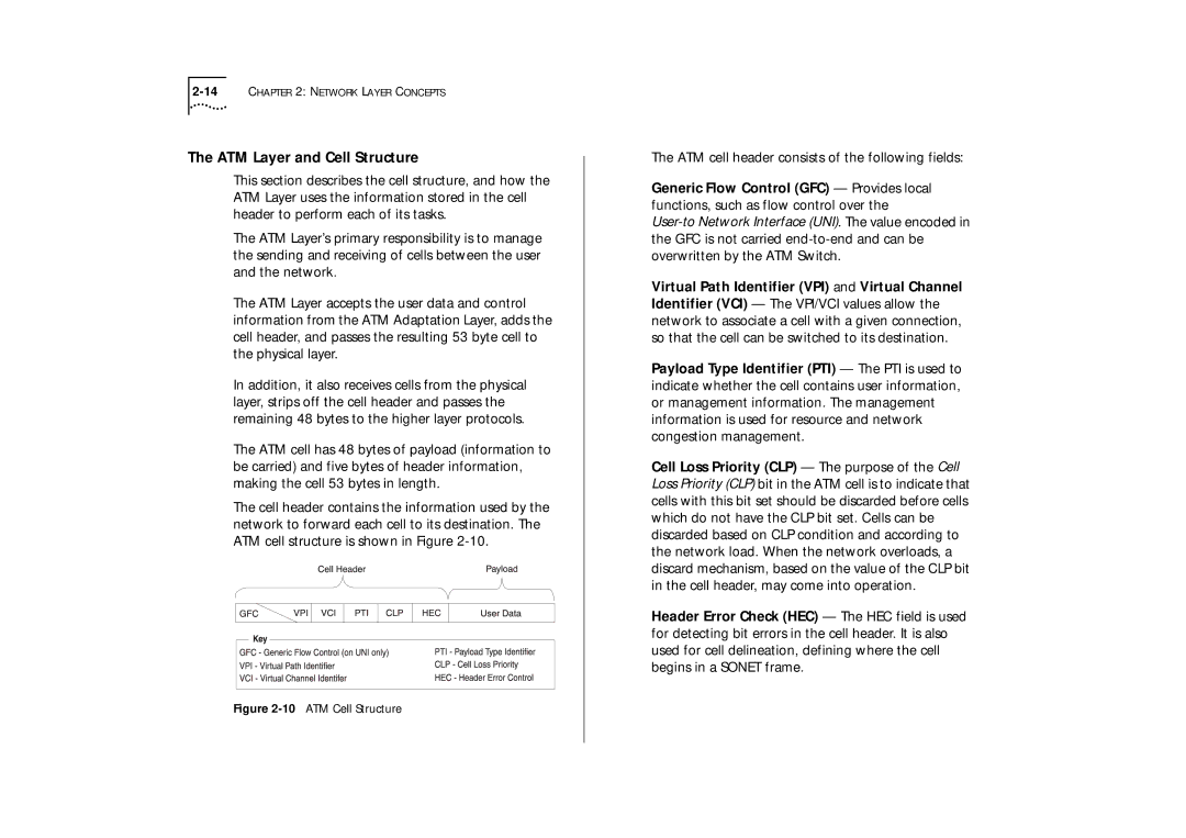
The cell header contains the information used by the network to forward each cell to its destination. The ATM cell structure is shown in Figure
Figure 2-10 ATM Cell Structure
The ATM cell header consists of the following fields:
Generic Flow Control (GFC) — Provides local functions, such as flow control over the
Virtual Path Identifier (VPI) and Virtual Channel Identifier (VCI) — The VPI/VCI values allow the network to associate a cell with a given connection, so that the cell can be switched to its destination.
Payload Type Identifier (PTI) — The PTI is used to indicate whether the cell contains user information, or management information. The management information is used for resource and network congestion management.
Cell Loss Priority (CLP) — The purpose of the Cell Loss Priority (CLP) bit in the ATM cell is to indicate that cells with this bit set should be discarded before cells which do not have the CLP bit set. Cells can be discarded based on CLP condition and according to the network load. When the network overloads, a discard mechanism, based on the value of the CLP bit in the cell header, may come into operation.
Header Error Check (HEC) — The HEC field is used for detecting bit errors in the cell header. It is also used for cell delineation, defining where the cell begins in a SONET frame.