e_hd250.book Page 28 Tuesday, October 24, 2006 3:11 PM
CONTROLS, INDICATORS AND CONNECTORS
Indications on the LCD Monitor and in the Viewfinder (Cont’d)
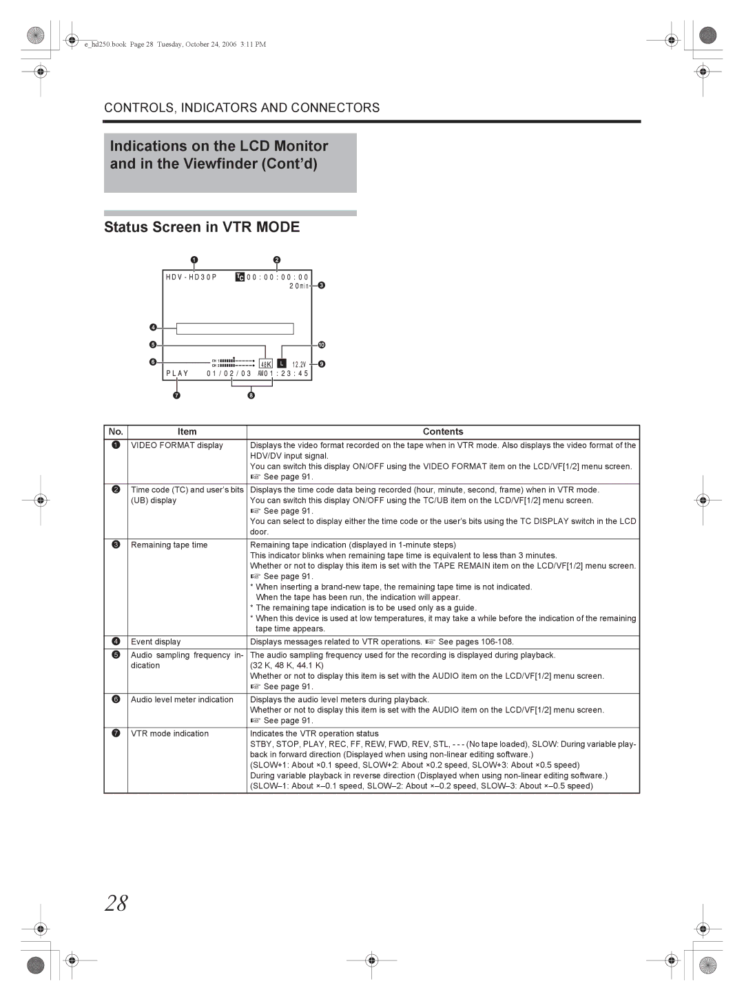
Status Screen in VTR MODE
1 | 2 |
| 3 |
4 |
|
5 | 0 |
6 | 9 |
| |
7 | 8 |
No. | Item | Contents |
1 | VIDEO FORMAT display | Displays the video format recorded on the tape when in VTR mode. Also displays the video format of the |
|
| HDV/DV input signal. |
|
| You can switch this display ON/OFF using the VIDEO FORMAT item on the LCD/VF[1/2] menu screen. |
|
| X See page 91. |
|
|
|
2 | Time code (TC) and user’s bits | Displays the time code data being recorded (hour, minute, second, frame) when in VTR mode. |
| (UB) display | You can switch this display ON/OFF using the TC/UB item on the LCD/VF[1/2] menu screen. |
|
| X See page 91. |
|
| You can select to display either the time code or the user’s bits using the TC DISPLAY switch in the LCD |
|
| door. |
|
|
|
3 | Remaining tape time | Remaining tape indication (displayed in |
|
| This indicator blinks when remaining tape time is equivalent to less than 3 minutes. |
|
| Whether or not to display this item is set with the TAPE REMAIN item on the LCD/VF[1/2] menu screen. |
|
| X See page 91. |
|
| * When inserting a |
|
| When the tape has been run, the indication will appear. |
|
| * The remaining tape indication is to be used only as a guide. |
|
| * When this device is used at low temperatures, it may take a while before the indication of the remaining |
|
| tape time appears. |
4 | Event display | Displays messages related to VTR operations. X See pages |
|
|
|
5 | Audio sampling frequency in- | The audio sampling frequency used for the recording is displayed during playback. |
| dication | (32 K, 48 K, 44.1 K) |
|
| Whether or not to display this item is set with the AUDIO item on the LCD/VF[1/2] menu screen. |
|
| X See page 91. |
|
|
|
6 | Audio level meter indication | Displays the audio level meters during playback. |
|
| Whether or not to display this item is set with the AUDIO item on the LCD/VF[1/2] menu screen. |
|
| X See page 91. |
|
|
|
7 | VTR mode indication | Indicates the VTR operation status |
|
| STBY, STOP, PLAY, REC, FF, REW, FWD, REV, STL, - - - (No tape loaded), SLOW: During variable play- |
|
| back in forward direction (Displayed when using |
|
| (SLOW+1: About ×0.1 speed, SLOW+2: About ×0.2 speed, SLOW+3: About ×0.5 speed) |
|
| During variable playback in reverse direction (Displayed when using |
|
|
28