e_hd250.book Page 21 Tuesday, October 24, 2006 3:11 PM
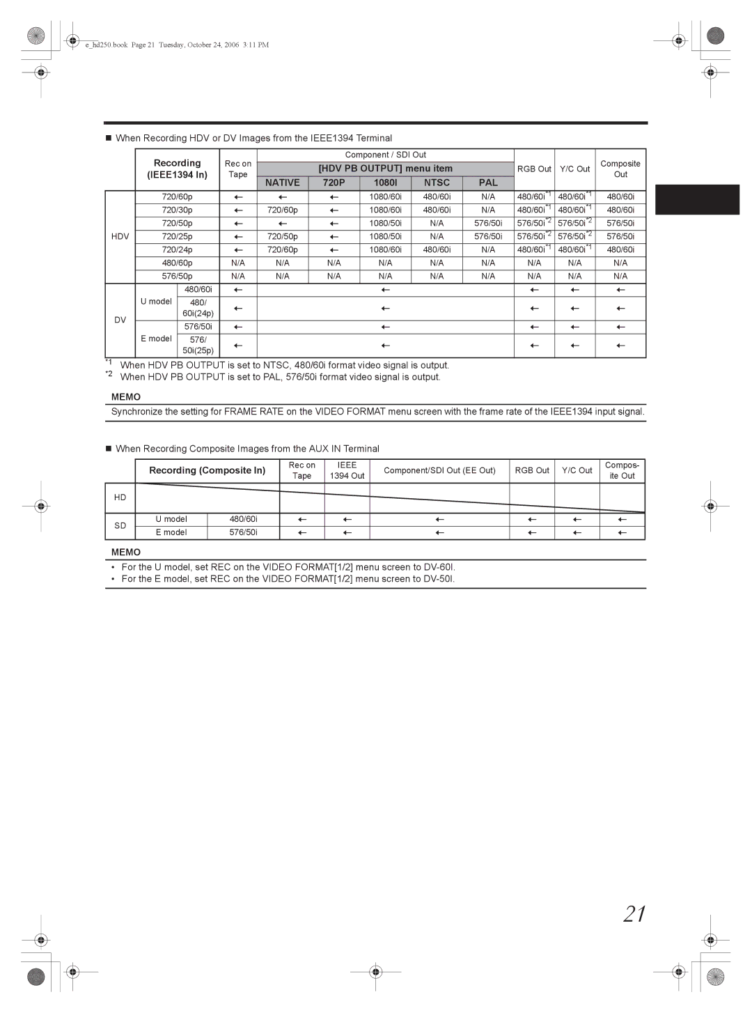
When Recording HDV or DV Images from the IEEE1394 Terminal
|
| Recording | Rec on |
| Component / SDI Out |
|
|
| Composite | |||
|
|
|
|
|
|
|
|
| ||||
|
|
| [HDV PB OUTPUT] menu item |
| RGB Out | Y/C Out | ||||||
|
| (IEEE1394 In) | Tape |
|
| Out | ||||||
|
| NATIVE | 720P | 1080I | NTSC | PAL |
|
| ||||
|
|
|
|
|
|
|
| |||||
|
| 720/60p | q | q | q | 1080/60i | 480/60i | N/A | 480/60i*1 | 480/60i*1 | 480/60i | |
|
| 720/30p | q | 720/60p | q | 1080/60i | 480/60i | N/A | 480/60i*1 | 480/60i*1 | 480/60i | |
|
| 720/50p | q | q | q | 1080/50i | N/A | 576/50i | 576/50i*2 | 576/50i*2 | 576/50i | |
HDV | 720/25p | q | 720/50p | q | 1080/50i | N/A | 576/50i | 576/50i*2 | 576/50i*2 | 576/50i | ||
|
| 720/24p | q | 720/60p | q | 1080/60i | 480/60i | N/A | 480/60i*1 | 480/60i*1 | 480/60i | |
|
| 480/60p | N/A | N/A | N/A | N/A | N/A | N/A | N/A | N/A | N/A | |
|
|
|
|
|
|
|
|
|
|
|
| |
|
| 576/50p | N/A | N/A | N/A | N/A | N/A | N/A | N/A | N/A | N/A | |
|
|
| 480/60i | q |
|
| q |
|
| q | q | q |
|
| U model | 480/ | q |
|
| q |
|
| q | q | q |
|
|
| 60i(24p) |
|
|
|
| |||||
| DV |
|
|
|
|
|
|
|
|
|
| |
|
| 576/50i | q |
|
| q |
|
| q | q | q | |
|
|
|
|
|
|
| ||||||
|
| E model |
|
|
|
|
|
|
|
|
|
|
|
| 576/ | q |
|
| q |
|
| q | q | q | |
|
|
| 50i(25p) |
|
|
|
| |||||
|
|
|
|
|
|
|
|
|
|
|
| |
*1 | When HDV PB OUTPUT is set to NTSC, 480/60i format video signal is output. |
|
|
|
| |||||||
*2 | When HDV PB OUTPUT is set to PAL, 576/50i format video signal is output. |
|
|
|
| |||||||
MEMO
Synchronize the setting for FRAME RATE on the VIDEO FORMAT menu screen with the frame rate of the IEEE1394 input signal.
When Recording Composite Images from the AUX IN Terminal
| Recording (Composite In) | Rec on | IEEE | Component/SDI Out (EE Out) | RGB Out | Y/C Out | Compos- | ||
| Tape | 1394 Out | ite Out | ||||||
|
|
|
|
|
| ||||
HD |
|
|
|
|
|
|
|
| |
|
|
|
|
|
|
|
|
| |
SD | U model | 480/60i | q | q | q | q | q | q | |
|
|
|
|
|
|
|
| ||
E model | 576/50i | q | q | q | q | q | q | ||
| |||||||||
MEMO
•For the U model, set REC on the VIDEO FORMAT[1/2] menu screen to
•For the E model, set REC on the VIDEO FORMAT[1/2] menu screen to
21