e_hd250.book Page 88 Tuesday, October 24, 2006 3:11 PM
MENU SCREENS
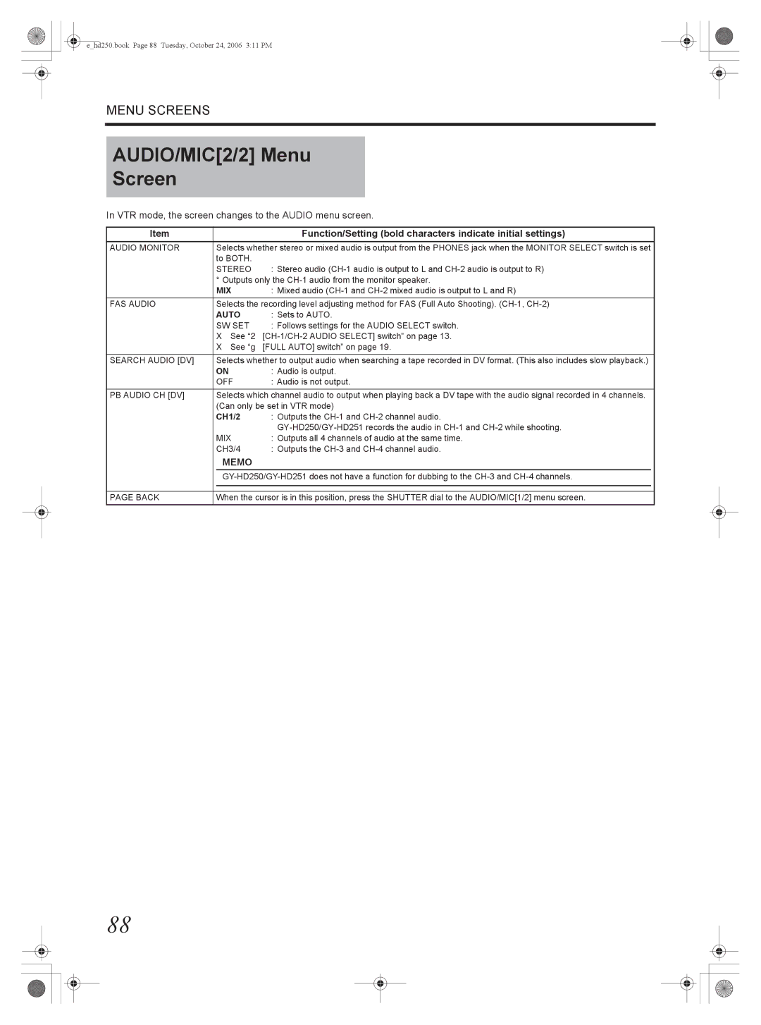
AUDIO/MIC[2/2] Menu
Screen
In VTR mode, the screen changes to the AUDIO menu screen.
Item |
|
| Function/Setting (bold characters indicate initial settings) |
|
AUDIO MONITOR |
| Selects whether stereo or mixed audio is output from the PHONES jack when the MONITOR SELECT switch is set |
| |
|
| to BOTH. |
|
|
|
| STEREO | : Stereo audio |
|
|
| * Outputs only the |
| |
|
| MIX | : Mixed audio |
|
FAS AUDIO | Selects the recording level adjusting method for FAS (Full Auto Shooting). |
| ||
|
| AUTO | : Sets to AUTO. |
|
|
| SW SET | : Follows settings for the AUDIO SELECT switch. |
|
|
| X See “2 |
| |
|
| X See “g [FULL AUTO] switch” on page 19. |
| |
|
|
| ||
SEARCH AUDIO [DV] | Selects whether to output audio when searching a tape recorded in DV format. (This also includes slow playback.) |
| ||
|
| ON | : Audio is output. |
|
|
| OFF | : Audio is not output. |
|
PB AUDIO CH [DV] | Selects which channel audio to output when playing back a DV tape with the audio signal recorded in 4 channels. |
| ||
|
| (Can only be set in VTR mode) |
| |
|
| CH1/2 | : Outputs the |
|
|
|
|
| |
|
| MIX | : Outputs all 4 channels of audio at the same time. |
|
|
| CH3/4 | : Outputs the |
|
|
| MEMO |
|
|
|
|
| ||
|
|
|
| |
|
|
| ||
PAGE BACK | When the cursor is in this position, press the SHUTTER dial to the AUDIO/MIC[1/2] menu screen. |
| ||
88