e_hd250.book Page 87 Tuesday, October 24, 2006 3:11 PM
AUDIO/MIC[1/2] Menu
Screen
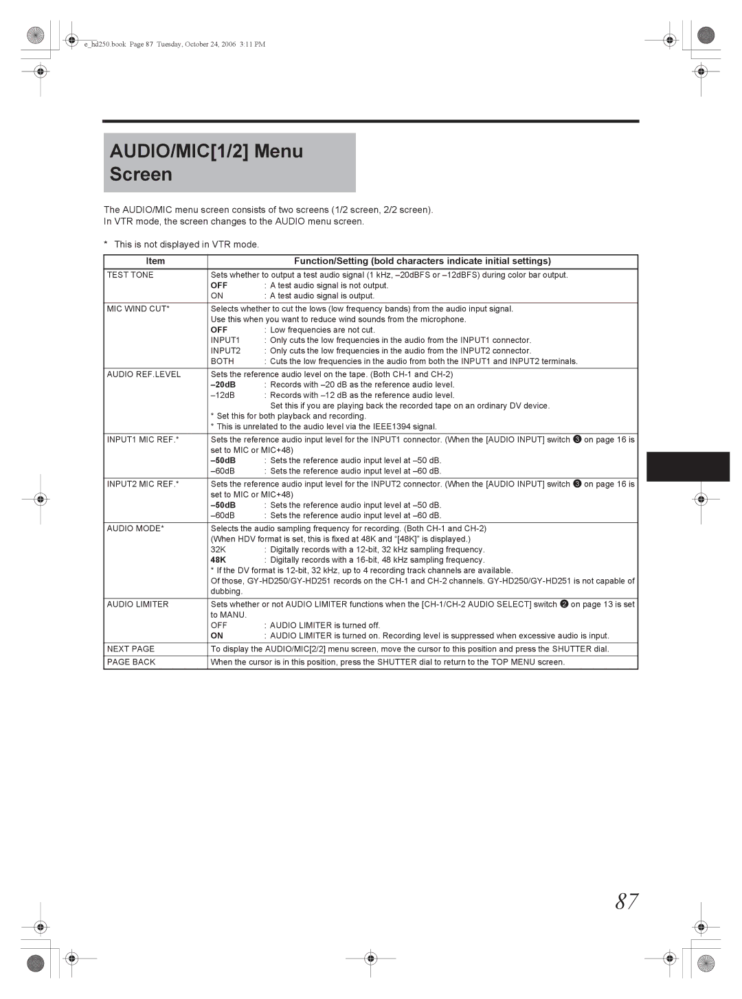
The AUDIO/MIC menu screen consists of two screens (1/2 screen, 2/2 screen).
In VTR mode, the screen changes to the AUDIO menu screen.
* This is not displayed in VTR mode.
Item |
| Function/Setting (bold characters indicate initial settings) |
TEST TONE | Sets whether to output a test audio signal (1 kHz, | |
| OFF | : A test audio signal is not output. |
| ON | : A test audio signal is output. |
MIC WIND CUT* | Selects whether to cut the lows (low frequency bands) from the audio input signal. | |
| Use this when you want to reduce wind sounds from the microphone. | |
| OFF | : Low frequencies are not cut. |
| INPUT1 | : Only cuts the low frequencies in the audio from the INPUT1 connector. |
| INPUT2 | : Only cuts the low frequencies in the audio from the INPUT2 connector. |
| BOTH | : Cuts the low frequencies in the audio from both the INPUT1 and INPUT2 terminals. |
|
| |
AUDIO REF.LEVEL | Sets the reference audio level on the tape. (Both | |
|
| : Records with |
| : Records with | |
|
| Set this if you are playing back the recorded tape on an ordinary DV device. |
| * Set this for both playback and recording. | |
| * This is unrelated to the audio level via the IEEE1394 signal. | |
INPUT1 MIC REF.* | Sets the reference audio input level for the INPUT1 connector. (When the [AUDIO INPUT] switch 3 on page 16 is | |
| set to MIC or MIC+48) | |
|
| : Sets the reference audio input level at |
| : Sets the reference audio input level at | |
INPUT2 MIC REF.* | Sets the reference audio input level for the INPUT2 connector. (When the [AUDIO INPUT] switch 3 on page 16 is | |
| set to MIC or MIC+48) | |
| : Sets the reference audio input level at | |
| : Sets the reference audio input level at | |
AUDIO MODE* | Selects the audio sampling frequency for recording. (Both | |
| (When HDV format is set, this is fixed at 48K and “[48K]” is displayed.) | |
| 32K | : Digitally records with a |
| 48K | : Digitally records with a |
| * If the DV format is | |
| Of those, | |
| dubbing. |
|
AUDIO LIMITER | Sets whether or not AUDIO LIMITER functions when the | |
| to MANU. |
|
| OFF | : AUDIO LIMITER is turned off. |
| ON | : AUDIO LIMITER is turned on. Recording level is suppressed when excessive audio is input. |
NEXT PAGE | To display the AUDIO/MIC[2/2] menu screen, move the cursor to this position and press the SHUTTER dial. | |
|
| |
PAGE BACK | When the cursor is in this position, press the SHUTTER dial to return to the TOP MENU screen. | |
|
|
|
87