e_hd250.book Page 17 Tuesday, October 24, 2006 3:11 PM
c d e
g[GENLOCK/AUX IN] GENLOCK/AUX IN terminal (BNC)
•Input synchronization signals in this terminal when externally synchronizing camera images or playback
images.
g
h
f
b |
VIDEO |
| |
- CH1 | i | |
CH2 - AUDIO OUT | ||
j | ||
1394 | k | |
IEEE | ||
|
a
Synchronization signal: BB (Black Burst) signal of SD or Tri sync signal of HD
•Input composite video signals to record images from an external device with this device.
•Select the signal to input with the [GENLOCK/AUX IN]
switch c.
X See “Using GENLOCK Functions” on page 66.
X See “Recording Composite Video Signals from an External Device” on page 65.
The sampling frequency for embedded audio is 48 kHz.
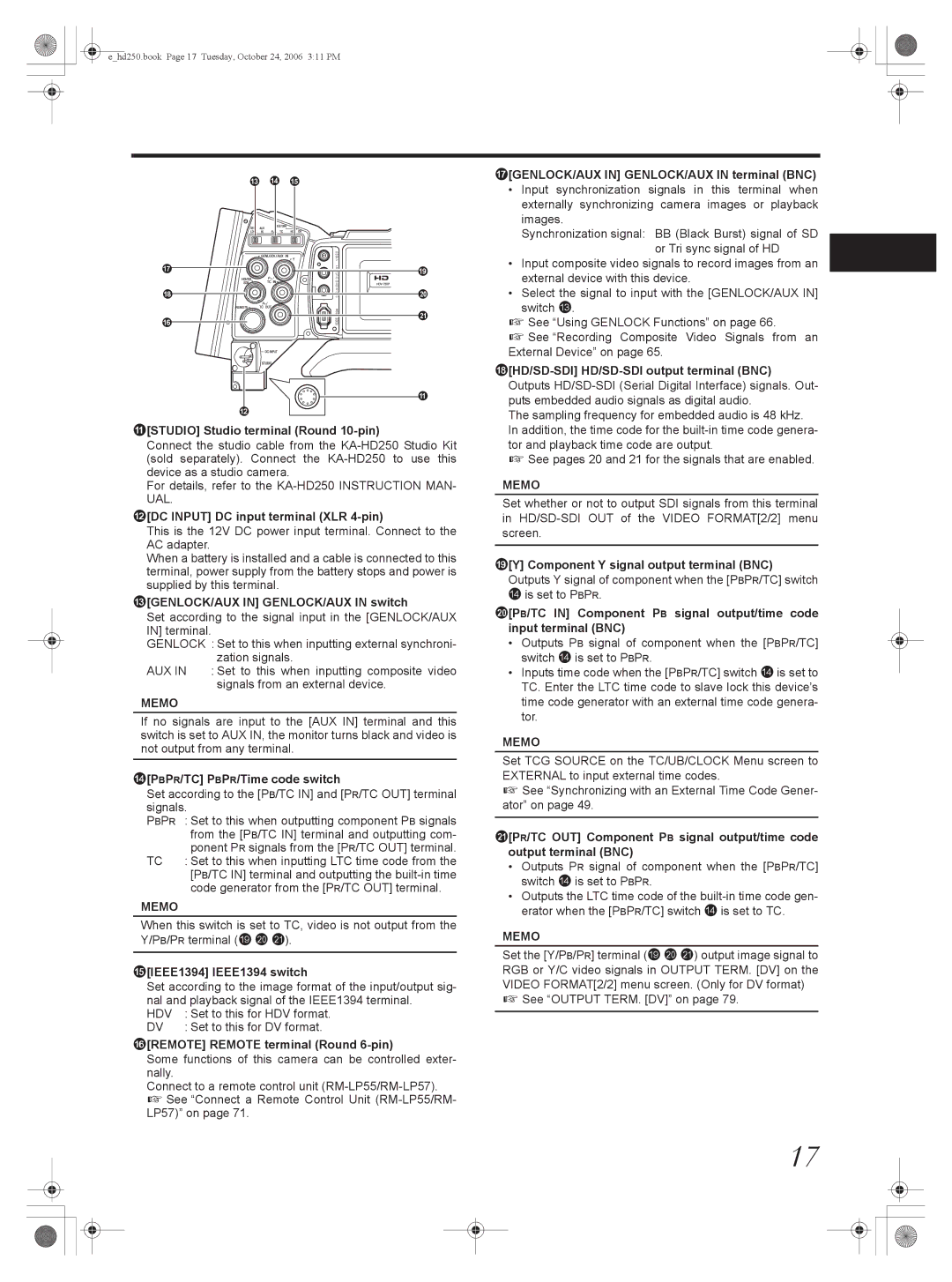
a[STUDIO] Studio terminal (Round 10-pin)
Connect the studio cable from the
For details, refer to the
b[DC INPUT] DC input terminal (XLR 4-pin)
This is the 12V DC power input terminal. Connect to the AC adapter.
When a battery is installed and a cable is connected to this terminal, power supply from the battery stops and power is supplied by this terminal.
c[GENLOCK/AUX IN] GENLOCK/AUX IN switch
Set according to the signal input in the [GENLOCK/AUX IN] terminal.
GENLOCK : Set to this when inputting external synchroni- zation signals.
AUX IN : Set to this when inputting composite video
signals from an external device.
MEMO
If no signals are input to the [AUX IN] terminal and this switch is set to AUX IN, the monitor turns black and video is not output from any terminal.
d[PBPR/TC] PBPR/Time code switch
Set according to the [PB/TC IN] and [PR/TC OUT] terminal signals.
PBPR : Set to this when outputting component PB signals from the [PB/TC IN] terminal and outputting com- ponent PR signals from the [PR/TC OUT] terminal.
TC : Set to this when inputting LTC time code from the [PB/TC IN] terminal and outputting the
MEMO
When this switch is set to TC, video is not output from the Y/PB/PR terminal (i j k).
e[IEEE1394] IEEE1394 switch
Set according to the image format of the input/output sig- nal and playback signal of the IEEE1394 terminal.
HDV | : Set to this for HDV format. |
DV | : Set to this for DV format. |
f[REMOTE] REMOTE terminal (Round 6-pin)
Some functions of this camera can be controlled exter- nally.
Connect to a remote control unit
In addition, the time code for the
X See pages 20 and 21 for the signals that are enabled.
MEMO
Set whether or not to output SDI signals from this terminal in
i[Y] Component Y signal output terminal (BNC) Outputs Y signal of component when the [PBPR/TC] switch
dis set to PBPR.
j[PB/TC IN] Component PB signal output/time code input terminal (BNC)
•Outputs PB signal of component when the [PBPR/TC] switch d is set to PBPR.
•Inputs time code when the [PBPR/TC] switch d is set to TC. Enter the LTC time code to slave lock this device’s time code generator with an external time code genera- tor.
MEMO
Set TCG SOURCE on the TC/UB/CLOCK Menu screen to EXTERNAL to input external time codes.
X See “Synchronizing with an External Time Code Gener- ator” on page 49.
k[PR/TC OUT] Component PB signal output/time code output terminal (BNC)
•Outputs PR signal of component when the [PBPR/TC] switch d is set to PBPR.
•Outputs the LTC time code of the
MEMO
Set the [Y/PB/PR] terminal (i j k) output image signal to RGB or Y/C video signals in OUTPUT TERM. [DV] on the VIDEO FORMAT[2/2] menu screen. (Only for DV format)
X See “OUTPUT TERM. [DV]” on page 79.
17