User’s Guide
Page
Table of Contents
Remote Operation
Command Reference
Iv LDX-3232
List of Figures
Vi LDX-3232
List of Tables
Viii LDX-3232
General Safety Considerations
Safety Information and the Manual
Safety Marking Symbols
Safety Symbols
Warranty
Claims for Shipping Damage
Model Number Serial Number End-User Name Company Phone Fax
Comments, Suggestions, and Problems
Description of the problem
Xiv LDX-3232
Product Overview
Introduction and Specifications
Grounding Requirements
Installing Your LDX-3232 High Compliance Current Source
AC Line Power Requirements
Initial Inspection
Operating the LDX-3232 Precision Current Source
Gpib Connector
Tilt-Foot Adjustment
Gpib Address
LDX-3232 Front View
Maintenance
Specifications
13 µs 12 ms
Type Pulse Width Delay
TTL
Description Model Number
Available Options and Accessories
Power On Sequence
Applying Power to Your LDX-3232
Power On State
Connecting to the Laser
Common Laser Cathode Photodiode Anode
Interlock Connections
Back Panel LD Connector
Grounding Considerations
Setting the PD Bias
Photodiode Connections
Display
Operating a Laser in Constant Current I Mode
Front Panel Operation
Setting Up the Precision Current Source
E R a T I O N
Entering Photodiode Responsivity Values
Operating a Laser in Constant Power P Mode
Method to calculate the responsivity is suggested below
LDX-3232 Error Indicators
Error Indicators
Error Indicators LDX-3232
Changing the Gpib Address
Reading the Gpib Address
Changing Operation from Local to Remote
LDX-3232 Current Source Command Set
Command Syntax
OFF OLD NEW True False SET Reset
LASLDI?
LDX-3232 Command Path Structure
Command Paths
IEEE488.2 Command Commands
LIM
LDX-3232 Frequently Used Commands
None
Operation Complete Definition
Status Reporting
Event and Condition Registers
LDX-3232 Status Reporting Schematic Diagram
Output Off Register
Disabled 10 N/A Enabled 11 N/A 12 N/A 13 N/A 14 N/A 15 N/A
LASerENABleOUTOFF nrf LASerENABleOUTOFF?
Error Messages
Command Timing and Completion
Response Message
Error Code Classifications
Mode
Used to enter the laser voltage calibration mode
Used to create a delay in the execution of further
Commands
Used to enter the laser current calibration mode
Returns the value of the LAS conditions enable register
Returns status of photodiode monitor power display
Enables Laser display to show parameter values
Sets the enable register for Laser conditions
Or P optical power
Used to return the optical power from monitor
Used to set the constant optical power setpoint, if
Used to enable/disable the front panel modulation input
Used to return the Laser setpoint tolerance value
Returns the status of the Term command
Powered up
Returns the elapsed time since the timer was last reset
Command Description Format
LDX-3232 Device-Dependent Commands
Delay
LDX-3232 Device-Dependent Command Reference
Calmd LAS Calpd
ERRors?
LASerCALMD
LASerCALMD?
Responsivity CAL PD parameter setting Syntax Diagram
Calibration for that bandwidth
Selected. This procedure is outlined in Chapter
LASerCALLDI
LAS CAL LDV
LASerCALLDI?
LASerCALLDV
LDI LAS CAL
LASerCALMDI
True measured value. This procedure is outlined in Chapter
LASerCALLDV?
LAS CAL IPD
LASerCALMDI?
LASerCOND?
MDI
LASerDEC
LASDIS?
LASerDISplay
LASerDISplay?
LAS DIS
LDI
LASerDISplayLDI
LASerDISplayLDI?
Lasdisldi
LASDISLDV?
Voltage measurement Syntax Diagram
LASerDISplayLDV
LASerDISplayLDV?
LAS DIS IPD
LASerDISplayMDI
LASerDISplayMDI?
LAS DIS MDI
LAS DIS MDP
LASerDISplayMDP
LASerDISplayMDP?
PPD
LAS DIS SET
LASerDISplayPARAM
LASerDISplaySET
LAS DIS Param
LASDISPLAYSET?
LASerENABleCOND
LASerDISplaySET?
LAS Enab Cond
LASerENABleCOND?
Bit
Lasenabevent
LASerENABleEVEnt
An nrf value whose sum represents the bits that are enabled
Action enables the Laser status event register so that
LAS Enab EVE
LASerENABleEVEnt?
LASerENABleOUTOFF
LAS Enab Outoff
LASerENABleOUTOFF?
LAS EVE
LASerENABleEVEnt command
Command while the condition status is constantly changing
LASerEVEnt?
Function for the Laser output
LASerINC
LAS LDI
This measurement is updated approximately once every 600 ms
LASerLDI
LASerLDI?
LAS LDV
LASerLDV
LASerLDV?
For LDV calibration
LAS LIM
LASerLIMitI2
LASerLIMitI2?
Limit in use depends on the Laser output range selection
LASLIMI4?
Displayed, and then releasing the SET switch
LASerLIMitI4
LASerLIMitI4?
MDP LAS LIM
LASerLIMitMDP
LASerLIMitMDP?
LASerLIMitV?
LASerLIMitV
MDP P PD setpoint would be used
LASerMDI
LASerMDI?
MDI LAS IPD
LAS Mdln
LASerMDLN
LASerMDLN?
MDP LAS
LASerMDP
LASerMDP?
LASerMODEIHBW
LAS Mode
LAS Mode Ihbw
LASerMODE?
Lasmodeilbw
LAS Mode MDP
LASerMODEILBW
LASerMODEMDP
LAS OUT
LASerOUTput
LASerOUTput?
LASRAN?
LASerRANge
LASerRANge?
LAS RAN
LASerSETMDI?
Where the response is the constant I setpoint value, in mA
30 µA, for use in constant P mode with Calpd =
LASerSETLDI?
100 µA
Where the response is the constand PPD setpoint, in mW
LASerSETMDP?
LASerSTEP
LAS TOL
LASerTOLerance command
LASerSTEP?
LASerTOLerance
MES
LASerTOLerance?
MESsage
Second is the time window, in seconds
RADix
MESsage?
Means hexadecimal, and OCT means octal
Term 0 command is sent or the LDX-3232 is powered off
RADix?
RAD
Time
LDX-3232 was last powered up
Time clock is independent of the Timer clock
Seconds since the last TIMER? query was issued
Since the last TIMER? query was issued
Timer
Last TIMER? query is returned
Saving and Recalling from the Front Panel
Functions and Features
Saving and Recalling Under Remote Operation
Using the Laser Compliance Voltage Adjustment
LDX-3232 Rear Panel
Using the LDX-3232 Current Source’s Trigger Function
BNC Interlock Usage Example
Modulating the Laser Current Source
Modulating the Laser Current Source
Functions and Features
Calibration Overview
Calibration and Troubleshooting
DMM
Description Manufacturer/Model Specification
Recommended Equipment
Current Limit
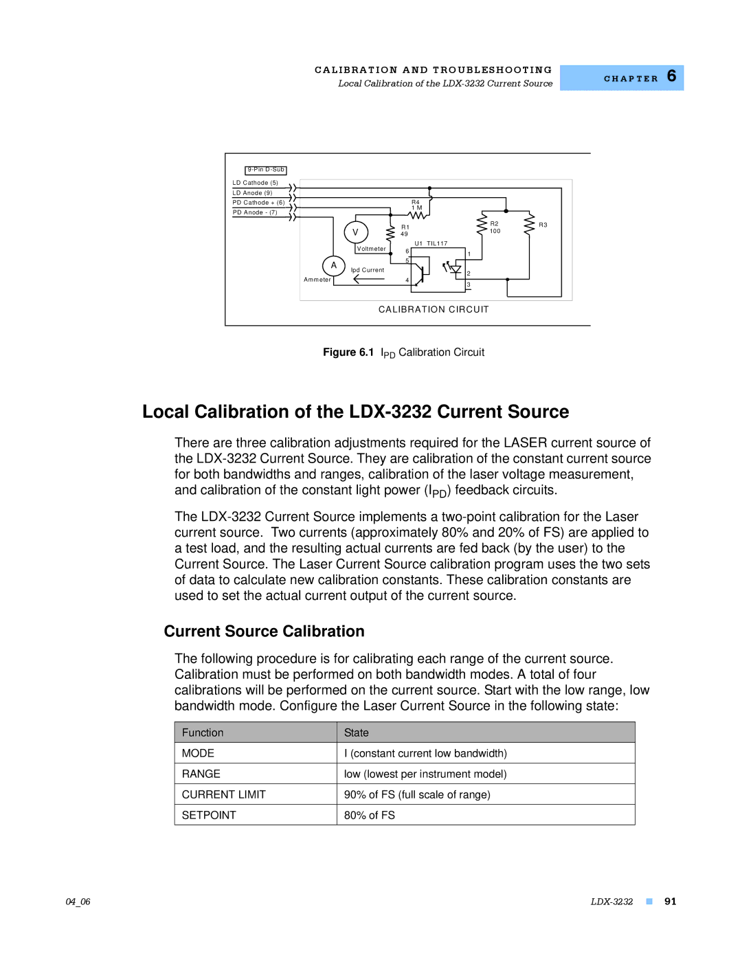
Local Calibration of the LDX-3232 Current Source
Current Source Calibration
Range
IPD Current Calibration
IPD Setpoint
Constant power
CAL PD
Set equal to zero
Set to FS full scale of range
Laser Mode
Laser Forward Voltage Measurement Calibration
2000 mA
Limit
Gpib Command
Remote Calibration of the LDX-3232 Current Source
Lasldi nrf value command
IPD Setpoint
Function State Gpib Command
Current source must be recalibrated
Troubleshooting Guide
General
EEPROM, Lllll will be displayed on the display the laser
Command
Feature can be defeated via the Lasenableoutoff
101
Response Message

