Return to Section TOC
Return to Section TOC
Return to Section TOC
Return to Section TOC
Return to Master TOC
Return to Master TOC
Return to Master TOC
Return to Master TOC
| THEORY OF OPERATION |
DC WELDING OUTPUT
|
|
| POLARITY SWITCH |
|
| |||
|
|
|
|
| BOARD | |||
|
|
|
| (DC POSITION) |
|
| ||
|
|
|
|
|
| WORK | ||
|
|
|
|
|
|
|
| |
|
|
|
|
|
|
|
| |
|
|
|
|
|
|
|
| TRANSFORMER |
LINE |
|
|
|
|
|
|
| ELECTRODE |
MAIN |
|
|
|
|
|
|
| |
SWITCH |
|
|
|
|
|
|
| |
TRANSFORMER |
|
|
|
|
|
|
| |
R | X2 |
| AC | DC+ |
|
|
| |
E |
| SHUNT |
|
| ||||
|
| SCR |
|
| ||||
C |
|
|
|
|
|
| ||
|
|
| BRIDGE |
|
|
| ||
O |
|
|
|
|
|
| ||
|
|
|
|
|
|
|
| |
N |
|
|
|
|
|
|
|
|
N |
|
|
|
|
|
|
|
|
E | X1 |
| AC | DC- |
|
|
| |
C |
|
| CHOKE |
|
| |||
T |
|
|
|
|
|
|
| |
| SIGNALSGATE |
|
|
|
|
|
| |
POWER |
|
|
|
|
|
| FEEDBACK | |
|
|
|
|
|
|
|
| |
FACTOR |
|
|
|
|
|
|
|
|
CAPACITORS |
|
|
|
|
|
|
| |
|
|
|
| ARC START |
|
| LCD DISPLAY | |
|
|
|
|
|
|
|
| |
| 115VAC | PROTECTION | 115 VAC | CONTROL | KEYPAD | |||
FAN |
|
| ||||||
| SNUBBER |
| GATE SIGNALS | BOARD |
| LED | ||
|
| BOARD |
|
| BOARD | |||
|
|
|
|
|
|
| ||
|
|
|
|
|
|
| KEYPAD | |
|
|
|
|
| 115 VAC |
|
| |
|
| 115 |
|
|
|
|
| |
|
|
|
|
|
|
|
| |
|
| VAC |
|
| 24 VAC |
|
| |
|
|
|
| CONTROL | 18 VAC |
|
| |
| 115 VAC |
|
| TRANSFORMER |
|
| ||
|
|
| 16 VAC |
|
| |||
|
|
|
|
|
|
| ||
RECEPTACLE |
|
|
|
|
|
| ||
|
|
|
|
|
|
| ||
|
| 115 VAC |
| HIGH VOLTAGE | HIGH FREQUENCY SPARK | |||
|
|
| TRANSFORMER | |||||
| REMOTE |
|
|
|
|
| ||
|
|
|
| CIRCUIT |
|
| ||
| RECEPTACLE |
|
|
|
|
| ||
|
|
|
|
|
|
| ||
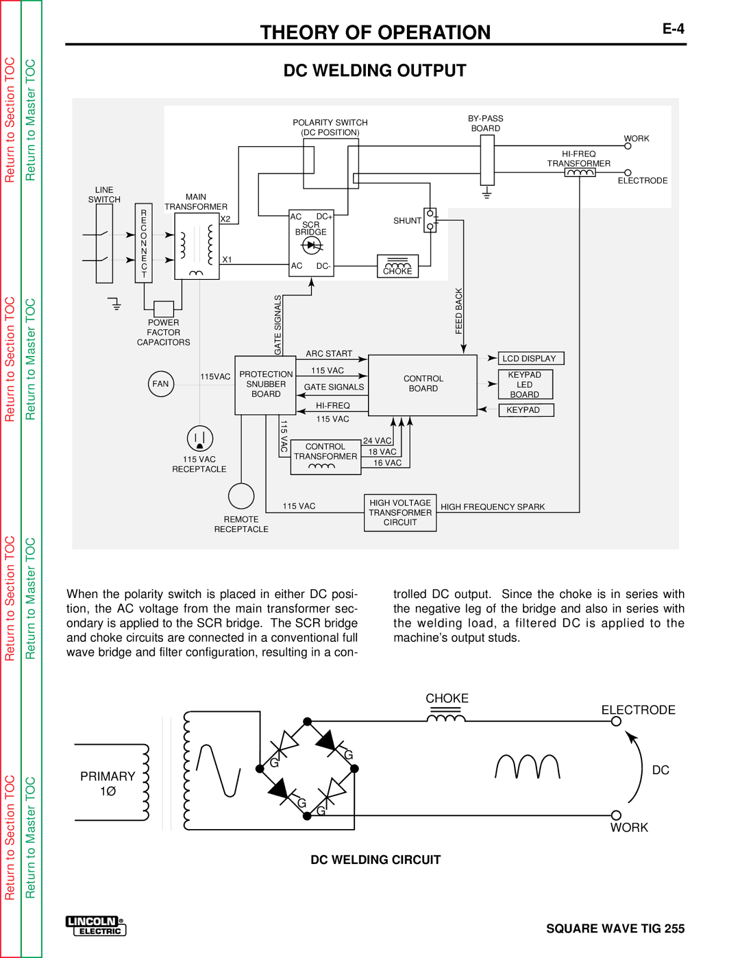
When the polarity switch is placed in either DC posi- | trolled DC output. Since the choke is in series with |
tion, the AC voltage from the main transformer sec- | the negative leg of the bridge and also in series with |
ondary is applied to the SCR bridge. The SCR bridge | the welding load, a filtered DC is applied to the |
and choke circuits are connected in a conventional full | machine’s output studs. |
wave bridge and filter configuration, resulting in a con- |
|
|
| CHOKE | |
|
| ELECTRODE | |
| G | G | |
PRIMARY | DC | ||
| |||
|
| ||
1Ø |
| G G | |
|
| ||
|
| WORK | |
|
| DC WELDING CIRCUIT |