Return to Section TOC
Return to Section TOC
Return to Master TOC
Return to Master TOC
THEORY OF OPERATION |
|
INPUT LINE VOLTAGE AND MAIN TRANSFORMER
|
|
|
| POLARITY |
|
| ||
|
|
|
|
|
| BOARD | ||
|
|
|
| SWITCH |
|
| ||
|
|
|
|
|
| WORK | ||
|
|
|
|
|
|
|
| |
|
|
|
|
|
|
|
| |
|
|
|
|
|
|
|
| TRANSFORMER |
LINE |
|
|
|
|
|
|
| ELECTRODE |
MAIN |
|
|
|
|
|
|
| |
SWITCH |
|
|
|
|
|
|
| |
TRANSFORMER |
|
|
|
|
|
|
| |
R | X2 |
| AC | DC+ |
|
|
| |
E |
| SHUNT |
|
| ||||
|
| SCR |
|
| ||||
C |
|
|
|
|
|
| ||
|
|
| BRIDGE |
|
|
| ||
O |
|
|
|
|
|
| ||
|
|
|
|
|
|
|
| |
N |
|
|
|
|
|
|
|
|
N |
|
|
|
|
|
|
|
|
E | X1 |
| AC | DC- |
|
|
| |
C |
|
| CHOKE |
|
| |||
T |
|
|
|
|
|
|
| |
| SIGNALSGATE |
|
|
|
|
|
| |
POWER |
|
|
|
|
|
| FEEDBACK | |
|
|
|
|
|
|
|
| |
FACTOR |
|
|
|
|
|
|
|
|
CAPACITORS |
|
|
|
|
|
|
| |
|
|
|
| ARC START |
|
| LCD DISPLAY | |
|
|
|
|
|
|
|
| |
| 115VAC | PROTECTION | 115 VAC | CONTROL | KEYPAD | |||
FAN |
|
| ||||||
| SNUBBER |
| GATE SIGNALS | BOARD |
| LED | ||
|
| BOARD |
|
| BOARD | |||
|
|
|
|
|
|
| ||
|
|
|
|
|
|
| KEYPAD | |
|
|
|
|
| 115 VAC |
|
| |
|
| 115 |
|
|
|
|
| |
|
|
|
|
|
|
|
| |
|
| VAC |
|
| 24 VAC |
|
| |
|
|
|
| CONTROL | 18 VAC |
|
| |
| 115 VAC |
|
| TRANSFORMER |
|
| ||
|
|
| 16 VAC |
|
| |||
|
|
|
|
|
|
| ||
RECEPTACLE |
|
|
|
|
|
| ||
|
|
|
|
|
|
| ||
|
| 115 VAC |
| HIGH VOLTAGE | HIGH FREQUENCY SPARK | |||
|
|
| TRANSFORMER | |||||
| REMOTE |
|
|
|
|
| ||
|
|
|
| CIRCUIT |
|
| ||
| RECEPTACLE |
|
|
|
|
| ||
|
|
|
|
|
|
| ||
Return to Section TOC
Return to Section TOC
Return to Master TOC
Return to Master TOC
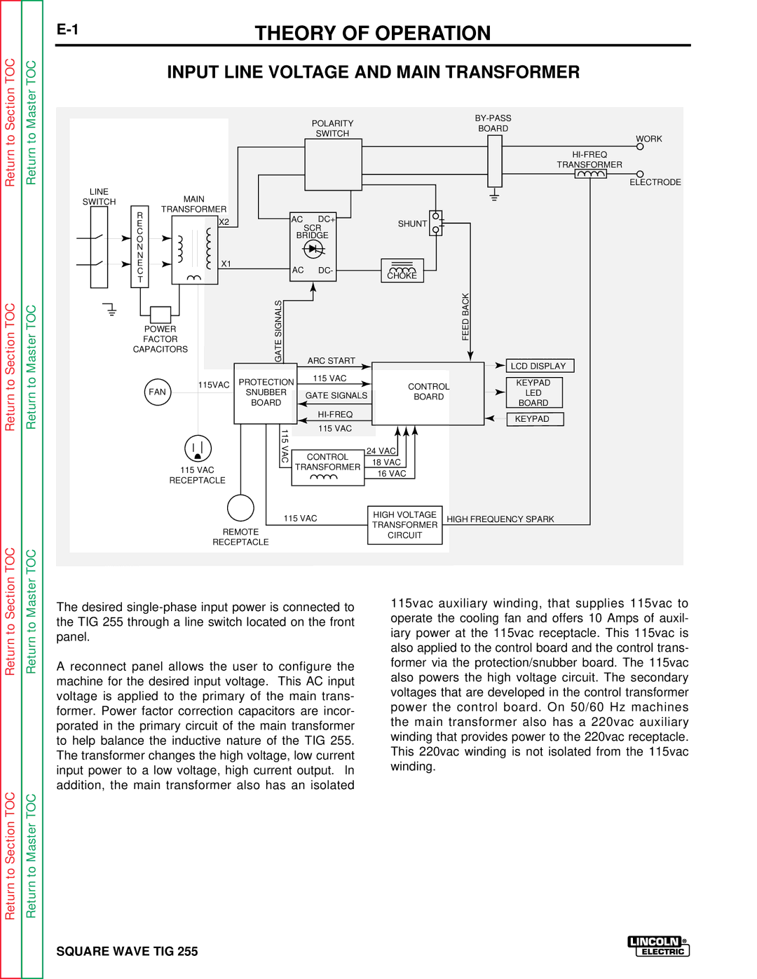
The desired
A reconnect panel allows the user to configure the machine for the desired input voltage. This AC input voltage is applied to the primary of the main trans- former. Power factor correction capacitors are incor- porated in the primary circuit of the main transformer to help balance the inductive nature of the TIG 255. The transformer changes the high voltage, low current input power to a low voltage, high current output. In addition, the main transformer also has an isolated
115vac auxiliary winding, that supplies 115vac to operate the cooling fan and offers 10 Amps of auxil- iary power at the 115vac receptacle. This 115vac is also applied to the control board and the control trans- former via the protection/snubber board. The 115vac also powers the high voltage circuit. The secondary voltages that are developed in the control transformer power the control board. On 50/60 Hz machines the main transformer also has a 220vac auxiliary winding that provides power to the 220vac receptacle. This 220vac winding is not isolated from the 115vac winding.