Return to Section TOC
Return to Section TOC
Return to Master TOC
Return to Master TOC
|
| TROUBLESHOOTING & REPAIR |
| |
CONTROL TRANSFORMER (T2) VOLTAGE TEST (continued) |
| |||
|
| SUPORT CASE BACK |
| |
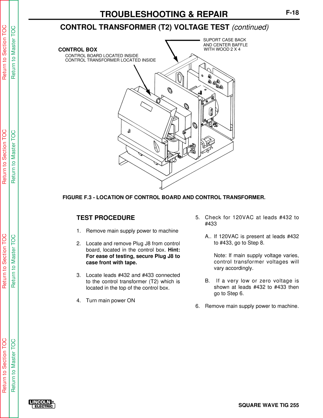
CONTROL BOX | AND CENTER BAFFLE |
| ||
WITH WOOD 2 X 4 |
| |||
CONTROL BOARD LOCATED INSIDE
CONTROL TRANSFORMER LOCATED INSIDE
FIGURE F.3 - LOCATION OF CONTROL BOARD AND CONTROL TRANSFORMER.
Return to Section TOC
Return to Section TOC
Return to Master TOC
Return to Master TOC
TEST PROCEDURE
1.Remove main supply power to machine
2.Locate and remove Plug J8 from control board, located in the control box. Hint:
For ease of testing, secure Plug J8 to case front with tape.
3.Locate leads #432 and #433 connected to the control transformer (T2) which is located in the top of the control box.
4.Turn main power ON
5.Check for 120VAC at leads #432 to #433
A..If 120VAC is present at leads #432 to #433, go to Step 8.
Note: If main supply voltage varies, control transformer voltages will vary accordingly.
B.If a very low or zero voltage is shown at leads #432 to #433 then go to Step 6.
6.Remove main supply power to machine.