Return to Section TOC
Return to Section TOC
Return to Section TOC
Return to Master TOC
Return to Master TOC
Return to Master TOC
THEORY OF OPERATION |
|
AC WELDING OUTPUT
|
|
| POLARITY SWITCH |
|
| |||
|
|
|
|
| BOARD | |||
|
|
|
| (AC POSITION) |
|
| ||
|
|
|
|
|
| WORK | ||
|
|
|
|
|
|
|
| |
|
|
|
|
|
|
|
| |
|
|
|
|
|
|
|
| TRANSFORMER |
LINE |
|
|
|
|
|
|
| ELECTRODE |
MAIN |
|
|
|
|
|
|
| |
SWITCH |
|
|
|
|
|
|
| |
TRANSFORMER |
|
|
|
|
|
|
| |
R | X2 |
| AC | DC+ |
|
|
| |
E |
| SHUNT |
|
| ||||
|
| SCR |
|
| ||||
C |
|
|
|
|
|
| ||
|
|
| BRIDGE |
|
|
| ||
O |
|
|
|
|
|
| ||
N |
|
|
|
|
|
|
|
|
N |
|
|
|
|
|
|
|
|
E | X1 |
| AC | DC- |
|
|
| |
C |
|
| CHOKE |
|
| |||
T |
|
|
|
|
|
|
| |
| SIGNALSGATE |
|
|
|
|
|
| |
POWER |
|
|
|
|
|
| FEEDBACK | |
|
|
|
|
|
|
|
| |
FACTOR |
|
|
|
|
|
|
|
|
CAPACITORS |
|
|
|
|
|
|
| |
|
|
|
| ARC START |
|
| LCD DISPLAY | |
|
|
|
|
|
|
|
| |
| 115VAC | PROTECTION | 115 VAC | CONTROL | KEYPAD | |||
FAN |
|
| ||||||
| SNUBBER |
| GATE SIGNALS | BOARD |
| LED | ||
|
| BOARD |
|
| BOARD | |||
|
|
|
|
|
|
| ||
|
|
|
|
|
|
| KEYPAD | |
|
|
|
|
| 115 VAC |
|
| |
|
| 115 |
|
|
|
|
| |
|
|
|
|
|
|
|
| |
|
| VAC |
|
| 24 VAC |
|
| |
|
|
|
| CONTROL | 18 VAC |
|
| |
| 115 VAC |
|
| TRANSFORMER |
|
| ||
|
|
| 16 VAC |
|
| |||
|
|
|
|
|
|
| ||
RECEPTACLE |
|
|
|
|
|
| ||
|
|
|
|
|
|
| ||
|
| 115 VAC |
| HIGH VOLTAGE | HIGH FREQUENCY SPARK | |||
|
|
| TRANSFORMER | |||||
| REMOTE |
|
|
|
|
| ||
|
|
|
| CIRCUIT |
|
| ||
| RECEPTACLE |
|
|
|
|
| ||
|
|
|
|
|
|
| ||
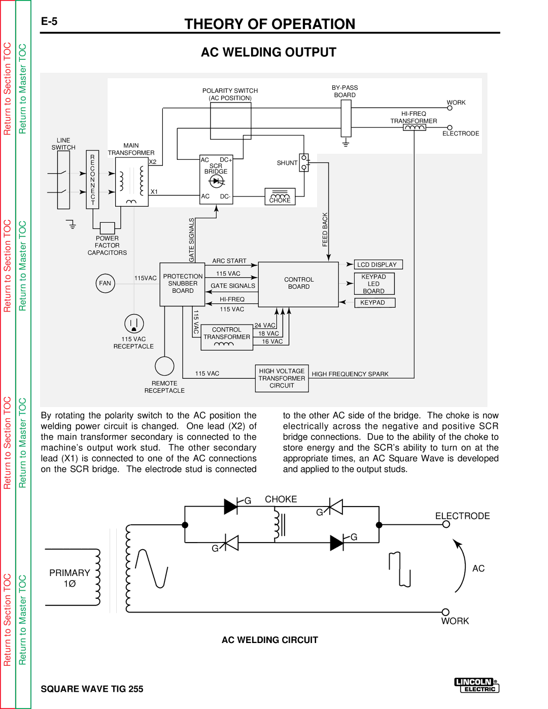
By rotating the polarity switch to the AC position the | to the other AC side of the bridge. The choke is now |
welding power circuit is changed. One lead (X2) of | electrically across the negative and positive SCR |
the main transformer secondary is connected to the | bridge connections. Due to the ability of the choke to |
machine’s output work stud. The other secondary | store energy and the SCR’s ability to turn on at the |
lead (X1) is connected to one of the AC connections | appropriate times, an AC Square Wave is developed |
on the SCR bridge. The electrode stud is connected | and applied to the output studs. |
Return to Section TOC
Return to Master TOC
PRIMARY 1Ø
![]() G CHOKE
G CHOKE
G![]()
![]() G
G
G![]()
AC WELDING CIRCUIT
ELECTRODE
AC
WORK