Return to Section TOC
Return to Section TOC
Return to Master TOC
Return to Master TOC
TROUBLESHOOTING & REPAIR |
|
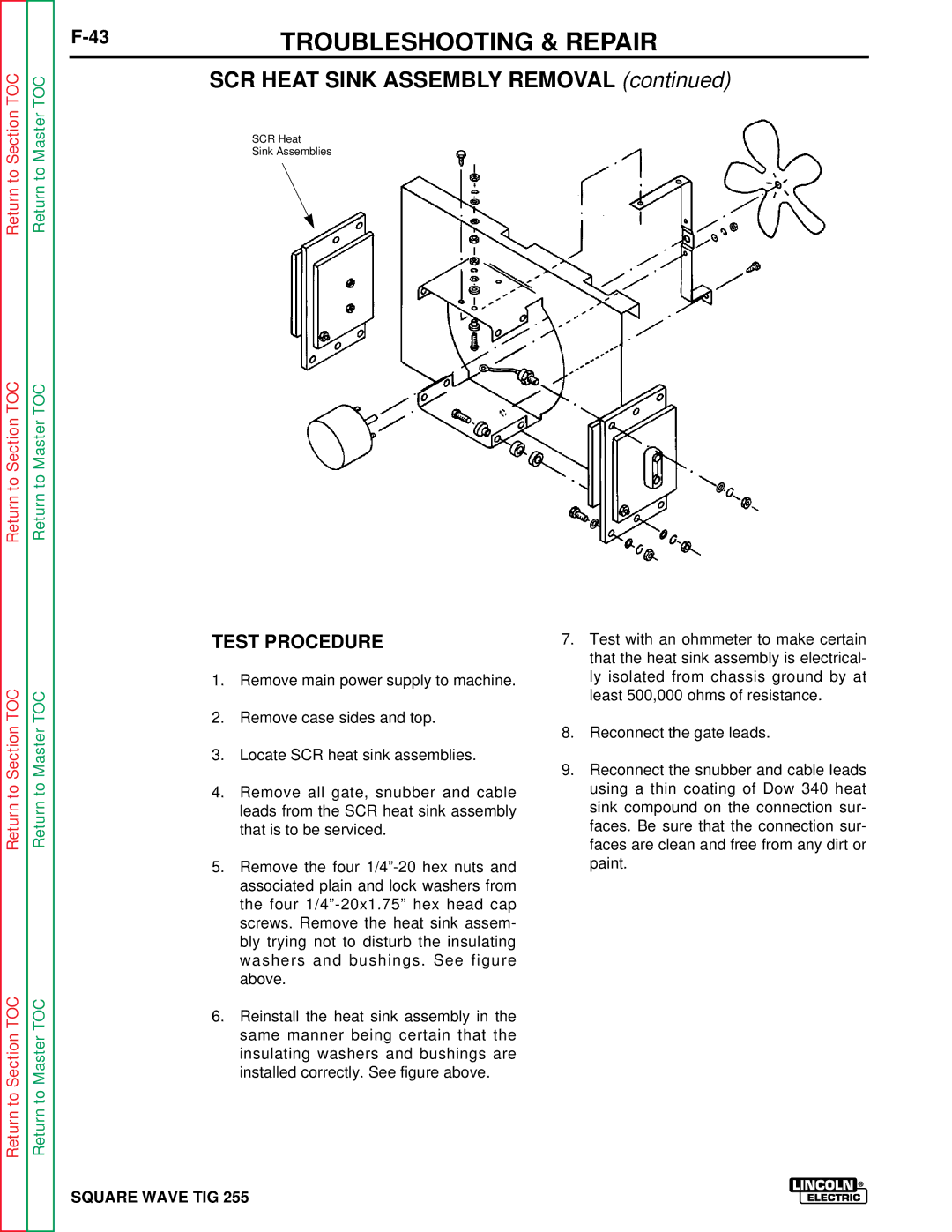
SCR HEAT SINK ASSEMBLY REMOVAL (continued)
SCR Heat
Sink Assemblies
Return to Section TOC
Return to Section TOC
Return to Master TOC
Return to Master TOC
TEST PROCEDURE
1.Remove main power supply to machine.
2.Remove case sides and top.
3.Locate SCR heat sink assemblies.
4.Remove all gate, snubber and cable leads from the SCR heat sink assembly that is to be serviced.
5.Remove the four
6.Reinstall the heat sink assembly in the same manner being certain that the insulating washers and bushings are installed correctly. See figure above.
7.Test with an ohmmeter to make certain that the heat sink assembly is electrical- ly isolated from chassis ground by at least 500,000 ohms of resistance.
8.Reconnect the gate leads.
9.Reconnect the snubber and cable leads using a thin coating of Dow 340 heat sink compound on the connection sur- faces. Be sure that the connection sur- faces are clean and free from any dirt or paint.