Return to Section TOC
Return to Section TOC
Section TOC
Return to Master TOC
Return to Master TOC
Master TOC
TROUBLESHOOTING & REPAIR
FLASHING AND ROTOR VOLTAGE TEST (continued)
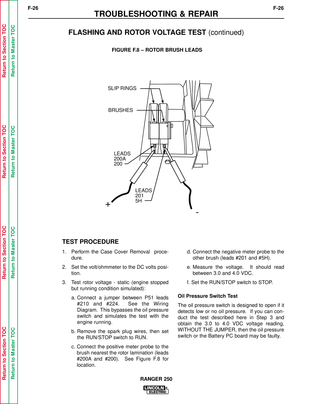
FIGURE F.8 – ROTOR BRUSH LEADS
SLIP RINGS
BRUSHES
LEADS 200A 200
| LEADS |
| 201 |
+ | 5H |
|
-
TEST PROCEDURE
Return to
Return to Section TOC
Return to
Return to Master TOC
1.Perform the Case Cover Removal proce- dure.
2.Set the volt/ohmmeter to the DC volts posi- tion.
3.Test rotor voltage - static (engine stopped but running condition simulated):
a.Connect a jumper between P51 leads #210 and #224. See the Wiring Diagram. This bypasses the oil pressure switch and simulates the test with the engine running.
b.Remove the spark plug wires, then set the RUN/STOP switch to RUN.
c.Connect the positive meter probe to the brush nearest the rotor lamination (leads #200A and #200). See Figure F.8 for location.
d. Connect the negative meter probe to the other brush (leads #201 and #5H).
e. Measure the voltage. It should read between 3.0 and 4.0 VDC.
f. Set the RUN/STOP switch to STOP.
Oil Pressure Switch Test
The oil pressure switch is designed to open if it detects low or no oil pressure. If you can con- duct the test described here in Step 3 and obtain the 3.0 to 4.0 VDC voltage reading, WITHOUT THE JUMPER, then the oil pressure switch or the Battery PC board may be faulty.