Return to Section TOC
Return to Master TOC
TROUBLESHOOTING & REPAIR
POWER MODULE TEST (continued)
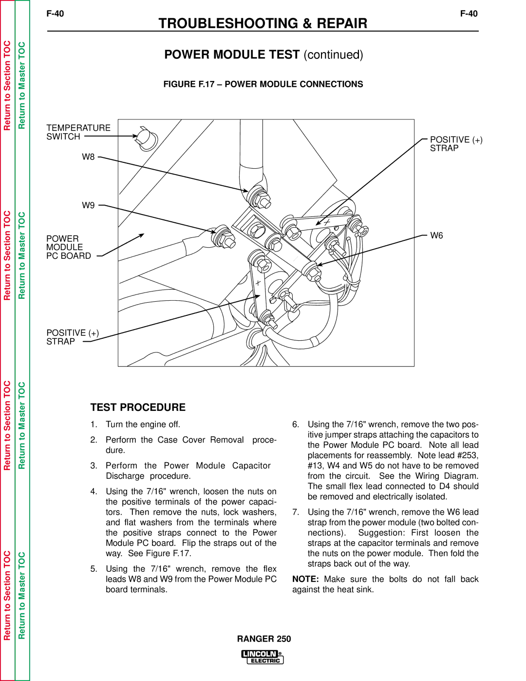
FIGURE F.17 – POWER MODULE CONNECTIONS
Return to Section TOC
Return to Section TOC
Return to Section TOC
Return to Master TOC
Return to Master TOC
Return to Master TOC
TEMPERATURE
SWITCH
W8
W9
POWER
MODULE
PC BOARD
POSITIVE (+)
STRAP
TEST PROCEDURE
1.Turn the engine off.
2.Perform the Case Cover Removal proce- dure.
3.Perform the Power Module Capacitor Discharge procedure.
4.Using the 7/16" wrench, loosen the nuts on the positive terminals of the power capaci- tors. Then remove the nuts, lock washers, and flat washers from the terminals where the positive straps connect to the Power Module PC board. Flip the straps out of the way. See Figure F.17.
5.Using the 7/16" wrench, remove the flex leads W8 and W9 from the Power Module PC board terminals.
POSITIVE (+)
STRAP
W6
6.Using the 7/16" wrench, remove the two pos- itive jumper straps attaching the capacitors to the Power Module PC board. Note all lead placements for reassembly. Note lead #253, #13, W4 and W5 do not have to be removed from the circuit. See the Wiring Diagram. The small flex lead connected to D4 should be removed and electrically isolated.
7.Using the 7/16" wrench, remove the W6 lead strap from the power module (two bolted con- nections). Suggestion: First loosen the straps at the capacitor terminals and remove the nuts on the power module. Then fold the straps back out of the way.
NOTE: Make sure the bolts do not fall back against the heat sink.