to Section TOC
to Master TOC
THEORY OF OPERATION
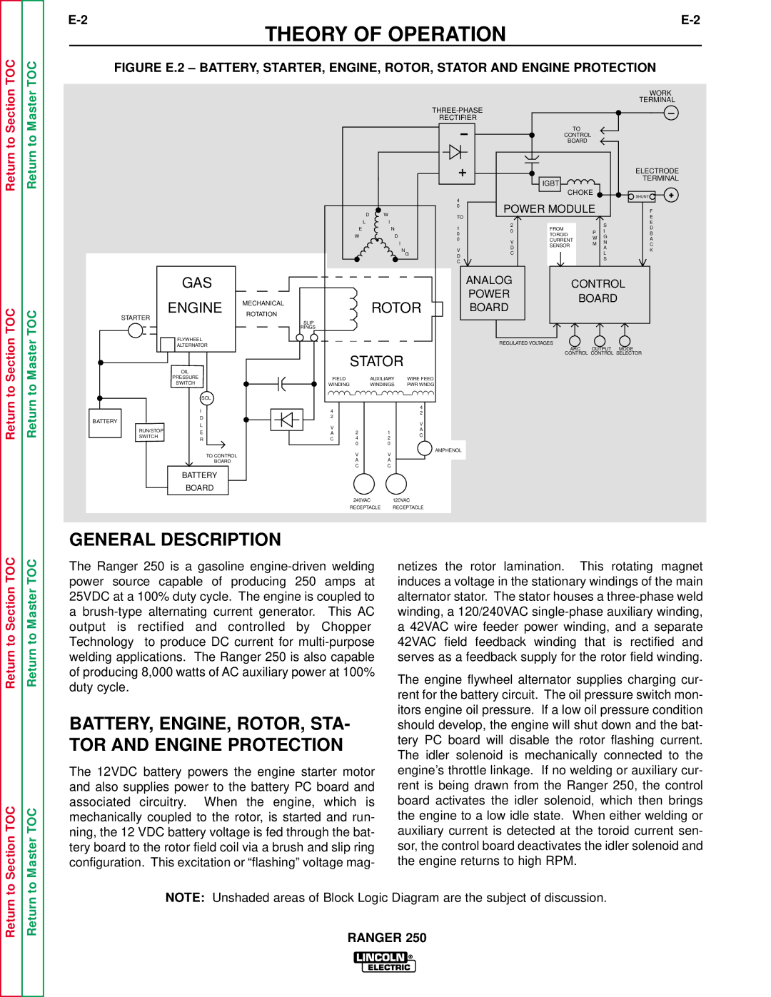
FIGURE E.2 – BATTERY, STARTER, ENGINE, ROTOR, STATOR AND ENGINE PROTECTION
WORK
TERMINAL
| __ | |
RECTIFIER |
|
|
TO
CONTROL
BOARD
D W
L I
EN
WD
I
N
G
+ | ELECTRODE | |
IGBT | TERMINAL | |
|
| |
CHOKE | SHUNT | + |
4 | POWER MODULE |
|
| |||
0 |
| F | ||||
|
| |||||
TO |
|
|
|
| E | |
| 2 |
|
| S | E | |
1 | FROM |
| D | |||
0 | P | I | ||||
0 | TOROID | B | ||||
| G | |||||
0 |
| CURRENT | W | A | ||
V | N | |||||
| SENSOR | M | C | |||
| D | A | ||||
V |
|
| K | |||
C |
|
| L | |||
D |
|
|
| |||
C | S |
|
to Section TOC
to Master TOC
STARTER
GAS
ENGINE MECHANICAL ROTATION
FLYWHEEL
ALTERNATOR
OIL
PRESSURE
SWITCH
|
|
| ANALOG | CONTROL |
|
|
| POWER | |
| ROTOR | BOARD | ||
| BOARD | |||
|
| |||
SLIP |
|
|
|
|
RINGS |
|
|
|
|
|
|
| REGULATED VOLTAGES |
|
|
|
|
| ARC OUTPUT MODE |
| STATOR |
|
| CONTROL CONTROL SELECTOR |
|
|
|
| |
FIELD | AUXILIARY | WIRE FEED |
|
|
WINDING | WINDINGS | PWR WNDG |
|
|
Return
Return
BATTERY
SOL
I
D
L
4 | 4 | |
2 | ||
2 | ||
| ||
V | V | |
|
RUN/STOPE
SWITCH
R
TO CONTROL
BOARD
BATTERY
BOARD
GENERAL DESCRIPTION
A | 2 | 1 | A |
C | 4 | 2 | C |
| |||
| 0 | 0 | AMPHENOL |
| V | V | |
|
|
AA
CC
240VAC 120VAC
RECEPTACLE RECEPTACLE
Return to Section TOC
to Section TOC
The Ranger 250 is a gasoline
BATTERY, ENGINE, ROTOR, STA- TOR AND ENGINE PROTECTION
The 12VDC battery powers the engine starter motor and also supplies power to the battery PC board and associated circuitry. When the engine, which is mechanically coupled to the rotor, is started and run- ning, the 12 VDC battery voltage is fed through the bat- tery board to the rotor field coil via a brush and slip ring configuration. This excitation or “flashing” voltage mag-
netizes the rotor lamination. This rotating magnet induces a voltage in the stationary windings of the main alternator stator. The stator houses a
The engine flywheel alternator supplies charging cur- rent for the battery circuit. The oil pressure switch mon- itors engine oil pressure. If a low oil pressure condition should develop, the engine will shut down and the bat- tery PC board will disable the rotor flashing current. The idler solenoid is mechanically connected to the engine’s throttle linkage. If no welding or auxiliary cur- rent is being drawn from the Ranger 250, the control board activates the idler solenoid, which then brings the engine to a low idle state. When either welding or auxiliary current is detected at the toroid current sen- sor, the control board deactivates the idler solenoid and the engine returns to high RPM.
