Return to Section TOC
Return to Master TOC
TROUBLESHOOTING & REPAIR
ENGINE/STATOR/ROTOR REMOVAL AND REPLACEMENT (continued)
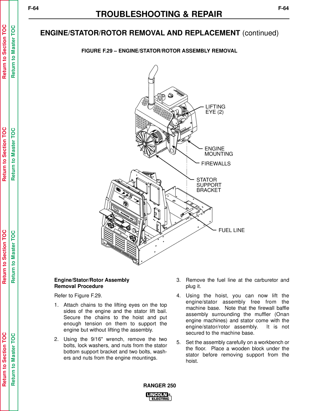
FIGURE F.29 – ENGINE/STATOR/ROTOR ASSEMBLY REMOVAL
Return to Section TOC
Return to Section TOC
Return to Section TOC
Return to Master TOC
Return to Master TOC
Return to Master TOC
Engine/Stator/Rotor Assembly
Removal Procedure
Refer to Figure F.29.
1.Attach chains to the lifting eyes on the top sides of the engine and the stator lift bail. Secure the chains to the hoist and put enough tension on them to support the engine but without lifting the assembly.
2.Using the 9/16" wrench, remove the two bolts, lock washers, and nuts from the stator bottom support bracket and two bolts, wash- ers and nuts from the engine mountings.
LIFTING
EYE (2)
 ENGINE
MOUNTING
FIREWALLS
STATOR
SUPPORT
BRACKET
FUEL LINE
3.Remove the fuel line at the carburetor and plug it.
4.Using the hoist, you can now lift the engine/stator assembly free from the machine base. Note that the firewall baffle assembly surrounding the muffler (Onan engine machines) and stator come with the engine/stator/rotor assembly. It is not secured to the machine base.
5.Set the assembly carefully on a workbench or the floor. Place a wooden block under the stator before removing support from the hoist.