Return to Section TOC
Return to Master TOC
TROUBLESHOOTING & REPAIR
OUTPUT RECTIFIER BRIDGE TEST (continued)
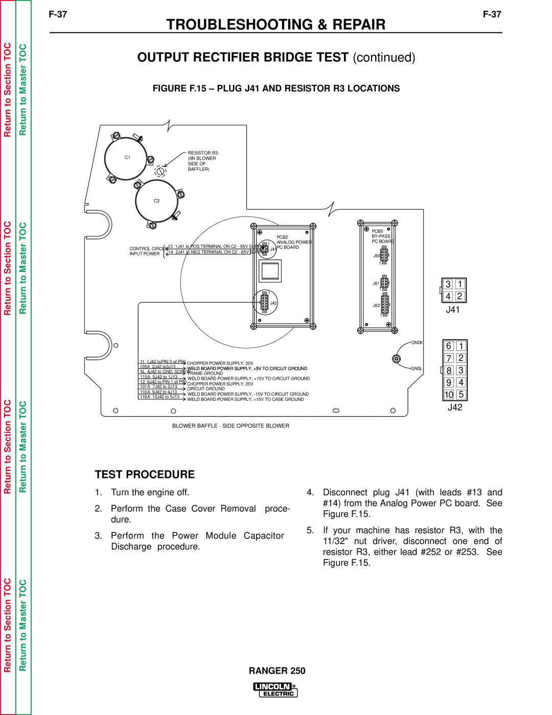
FIGURE F.15 – PLUG J41 AND RESISTOR R3 LOCATIONS
RESISTOR R3
C1(0N BLOWER
SIDE OF
BAFFLER)
C2
to Section TOC
to Master TOC
CONTROL CIRCUIT |
| 13 1J41 to POS TERMINAL ON C2 - 85V SUPPLY |
|
INPUT POWER | 14 2J41 to NEG TERMINAL ON C2 - 85V SUPPLY |
| |
|
| ||
|
| PCB5 |
| PCB2 | |
1 | ANALOG POWER | PC BOARD |
|
|
J41 PC BOARD
J60
1
J61
3 | 1 |
Return to Section TOC
Return to Master TOC
11 1J42 toPIN 3 of P50 |
|
|
| CHOPPER POWER SUPPLY, 20V |
105A 2J42 to3J13 |
|
|
| |
|
|
| WELD BOARD POWER SUPPLY, +5V TO CIRCUIT GROUND | |
5L 4J42 to GND. SCREW |
|
|
| |
|
|
| FRAME GROUND | |
115A 5J42 to 1J13 |
|
|
| |
|
|
| WELD BOARD POWER SUPPLY, +15V TO CIRCUIT GROUND | |
12 6J42 to PIN 1 of P50 |
|
|
| |
|
|
| CHOPPER POWER SUPPLY, 20V | |
101A 7J42 to 2J13 |
|
|
| |
|
|
| CIRCUIT GROUND | |
116A 9J42 to 4J13 |
|
|
| |
|
|
| WELD BOARD POWER SUPPLY, | |
118A 10J42 to 5J13 |
|
|
| |
|
|
| WELD BOARD POWER SUPPLY, +15V TO CASE GROUND | |
|
|
|
|
BLOWER BAFFLE - SIDE OPPOSITE BLOWER
TEST PROCEDURE
1.Turn the engine off.
2.Perform the Case Cover Removal proce- dure.
3.Perform the Power Module Capacitor Discharge procedure.
GND K
6 1
7 ![]()
![]() 2
2
GND L | 8 | 3 |
|
|
9 ![]()
![]() 4
4
10![]()
![]() 5
5
J42
4.Disconnect plug J41 (with leads #13 and #14) from the Analog Power PC board. See Figure F.15.
5.If your machine has resistor R3, with the 11/32" nut driver, disconnect one end of resistor R3, either lead #252 or #253. See Figure F.15.
Return to Section TOC
Return to Master TOC
