Return to Section TOC
Return to Section TOC
Return to Master TOC
Return to Master TOC
TROUBLESHOOTING & REPAIR
STATOR VOLTAGE TESTS (continued)
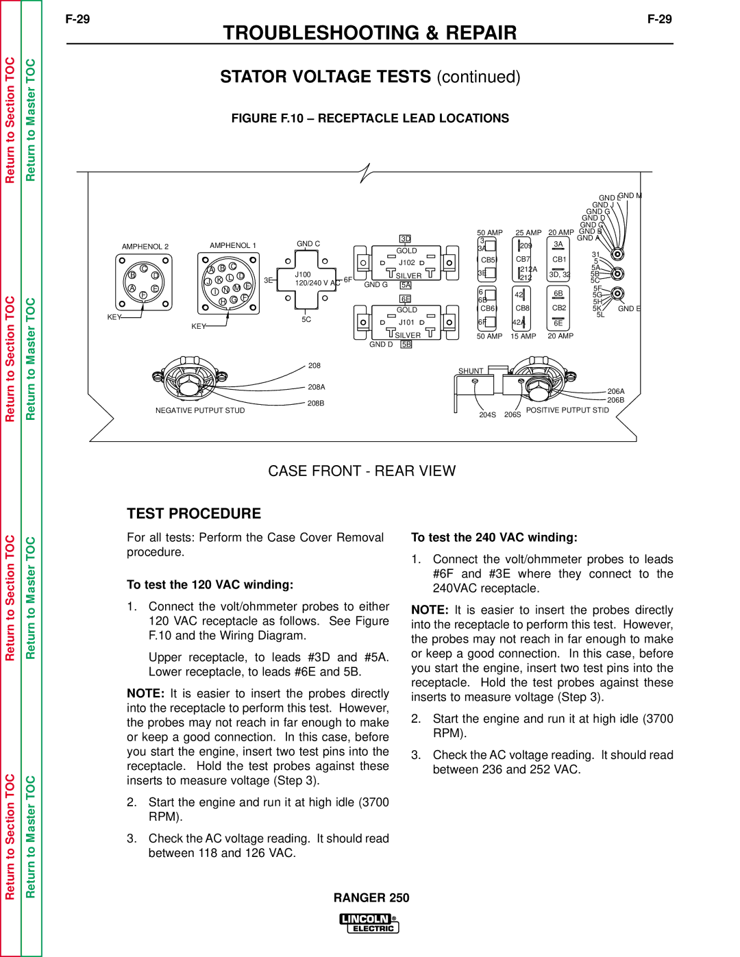
FIGURE F.10 – RECEPTACLE LEAD LOCATIONS
|
|
|
|
|
|
|
|
|
|
|
|
|
|
|
| GND L GND M | |
|
|
|
|
|
|
|
|
|
|
|
|
|
|
|
| GND J | |
|
|
|
|
|
|
|
|
|
|
|
|
|
|
|
| GND G |
|
|
|
|
|
|
|
|
|
|
|
|
|
|
|
|
| GND D |
|
|
|
|
|
|
|
|
|
|
|
|
|
|
|
|
| GND C |
|
|
|
|
|
|
|
|
|
|
|
| 3D | 50 AMP | 25 AMP | 20 AMP | GND B |
| |
AMPHENOL 2 | AMPHENOL 1 |
| GND C |
| 3 |
| 209 | 3A | GND A |
| |||||||
|
| GOLD | 3A |
|
|
| |||||||||||
|
|
|
|
| 31 |
| |||||||||||
|
|
|
|
|
|
|
|
|
|
|
|
|
|
|
| ||
|
|
|
|
|
|
|
|
|
|
|
| CB5 | CB7 | CB1 |
| ||
|
|
|
|
| C |
|
|
|
|
| J102 | 5 |
| ||||
| C | A |
| B |
|
|
|
|
|
| 3E |
| 212A |
| 5A |
| |
B | D |
|
| K | L | D | 3E | J100 | 6F | SILVER |
| 212 | 3D, 32 | 5B |
| ||
J |
|
|
|
| |||||||||||||
|
|
|
|
| E | 120/240 V AC | 5A |
|
|
|
| 5C |
| ||||
A | E |
| I | N | M |
|
| GND G | 6 |
|
| 6B | 5F |
| |||
|
|
|
|
|
| 42 |
| ||||||||||
| F |
| H | G |
| F |
|
|
| 6E | 5G |
| |||||
|
|
|
|
|
|
|
| 6B | CB8 | CB2 | 5H |
| |||||
|
|
|
|
|
|
|
|
|
|
| GOLD | CB6 | 5K | GND E | |||
KEY |
|
|
|
|
|
|
|
| 5C |
| J101 | 6F | 42A |
| 5L |
| |
|
|
|
|
|
|
|
|
| 6E |
|
| ||||||
|
| KEY |
|
|
|
|
|
|
|
|
| ||||||
|
|
|
|
|
|
|
|
|
|
|
| ||||||
|
|
|
|
|
|
|
|
|
|
|
|
|
|
|
|
| |
|
|
|
|
|
|
|
|
|
| GND D | SILVER | 50 AMP | 15 AMP | 20 AMP |
|
| |
|
|
|
|
|
|
|
|
|
| 5B |
|
|
|
|
|
| |
|
|
|
|
|
|
|
|
| 208 |
|
| SHUNT |
|
|
|
|
|
|
|
|
|
|
|
|
|
|
|
|
|
|
|
|
|
| |
|
|
|
|
|
|
|
|
| 208A |
|
|
|
|
|
|
| 206A |
|
|
|
|
|
|
|
|
|
|
|
|
|
|
|
|
| |
|
|
|
|
|
|
|
|
| 208B |
|
|
|
|
|
|
| 206B |
| NEGATIVE PUTPUT STUD |
|
|
|
|
|
|
| POSITIVE PUTPUT STID |
| |||||||
|
|
|
|
|
|
| 204S | 206S |
| ||||||||
|
|
|
|
|
|
|
|
|
|
|
|
|
|
|
| ||
CASE FRONT - REAR VIEW
Return to Section TOC
Return to Section TOC
Return to Master TOC
Return to Master TOC
TEST PROCEDURE
For all tests: Perform the Case Cover Removal procedure.
To test the 120 VAC winding:
1.Connect the volt/ohmmeter probes to either 120 VAC receptacle as follows. See Figure F.10 and the Wiring Diagram.
Upper receptacle, to leads #3D and #5A. Lower receptacle, to leads #6E and 5B.
NOTE: It is easier to insert the probes directly into the receptacle to perform this test. However, the probes may not reach in far enough to make or keep a good connection. In this case, before you start the engine, insert two test pins into the receptacle. Hold the test probes against these inserts to measure voltage (Step 3).
2.Start the engine and run it at high idle (3700 RPM).
3.Check the AC voltage reading. It should read between 118 and 126 VAC.
To test the 240 VAC winding:
1.Connect the volt/ohmmeter probes to leads #6F and #3E where they connect to the 240VAC receptacle.
NOTE: It is easier to insert the probes directly into the receptacle to perform this test. However, the probes may not reach in far enough to make or keep a good connection. In this case, before you start the engine, insert two test pins into the receptacle. Hold the test probes against these inserts to measure voltage (Step 3).
2.Start the engine and run it at high idle (3700 RPM).
3.Check the AC voltage reading. It should read between 236 and 252 VAC.